
Automatic variable control surface speed reducing mechanism with feedback for pneumatic test
A technology of wind test and deceleration mechanism, which is applied in the field of aerospace aerodynamics, can solve the problems of consuming resources and time, achieve the effect of ensuring the accuracy of angle adjustment and eliminating motion jamming
Patent Information
- Authority / Receiving Office
- CN · China
- Patent Type
- Applications(China)
- Current Assignee / Owner
- Publication Date
- 2020-06-26
- Estimated Expiration
- Not applicable · inactive patent
Smart Images
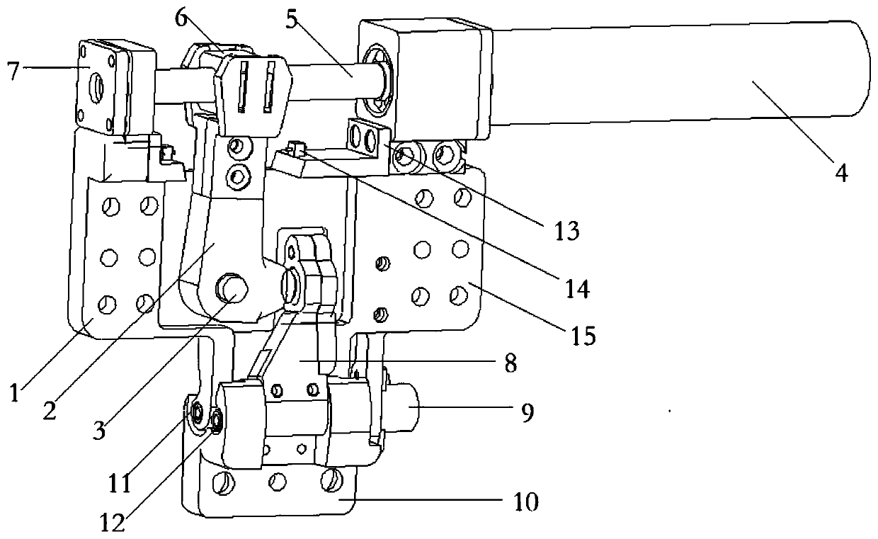
Figure 1 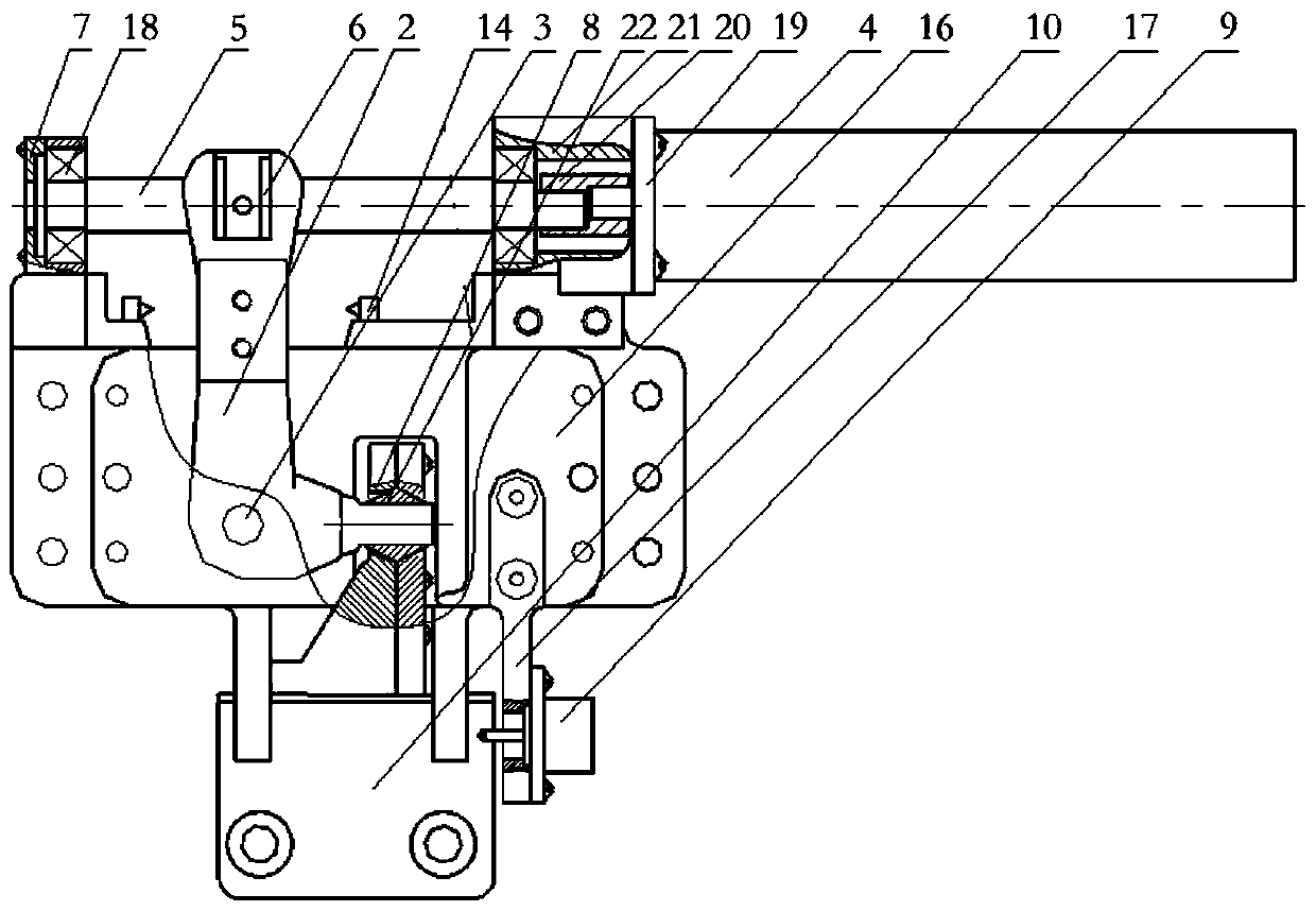
Figure 2 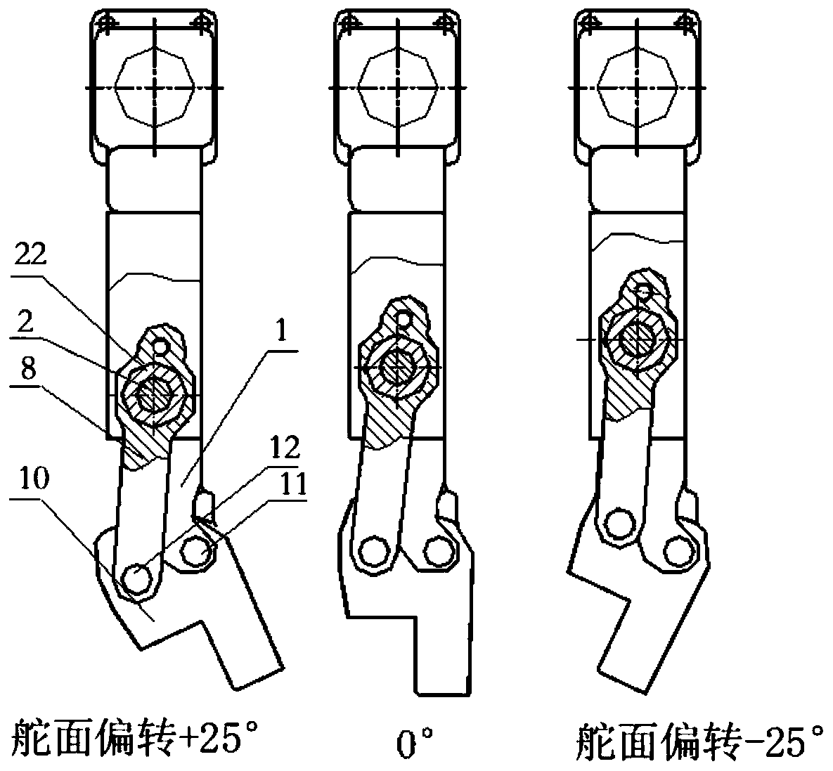
Figure 3
Abstract
Description
technical field
[0001] The invention relates to an automatic variable rudder surface deceleration mechanism with feedback for aerodynamic tests, which belongs to the technical field of aerospace aerodynamics. Background technique
[0002] The wind tunnel test is based on the principle of relativity of motion. The model or object of the aircraft is fixed in the artificial environment on the ground, and the air flow is artificially created to simulate various complex flight states in the air to obtain test data.
[0003] During the wind tunnel test, the model wing needs to stay at different angles for a certain period of time according to the set procedure to carry out the blowing test. Most of the existing pneumatic test rooms are manually operated by workers, and the efficiency is low. Some aerodynamic tests are carried out in a sealed cabin. Every time an angle is changed, workers need to release the pressure before entering the test cabin to operate the wing angle. After ...
Examples
Embodiment Construction
[0024] The present invention will be described in detail below with reference to the accompanying drawings and examples.
[0025] as attached figure 1 and 2 As shown, the present invention provides an automatic rudder surface deceleration mechanism with feedback for aerodynamic tests, the mechanism includes a left support 1, a right support 15, a motor 4, a cover plate 16, a shift fork 2, a nut 6, and a screw rod 5. Spherical push rod 8, ball head 22 and rudder surface mounting seat 10;
[0026] The screw mandrel 5 and the motor 4 are designed separately. The two ends of the screw mandrel 5 are supported on the left support 1 and the right support 15 through the bearing 18. The motor 4 on the support 15 is connected with the screw mandrel 5 through a coupling 20 . The motor 4 drives the screw mandrel 5 to rotate coaxially after being decelerated by the gear box reducer. The two cover plates 16 respectively form an installation cavity through up and down on the front and re...