
Thyristor control series compensation control method for low-voltage power distribution network
A low-voltage distribution network and series compensation technology, applied in reactive power compensation, reactive power adjustment/elimination/compensation, electrical components, etc., can solve the problem that it is difficult to effectively control the low voltage of the distribution network and cannot directly apply LD-TCSC And other issues
Patent Information
- Authority / Receiving Office
- CN · China
- Patent Type
- Applications(China)
- Current Assignee / Owner
- Publication Date
- 2020-08-28
Smart Images
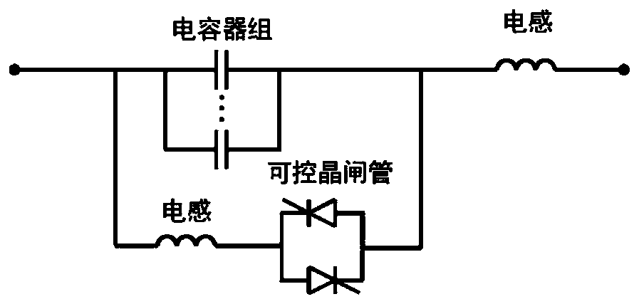
Figure 1 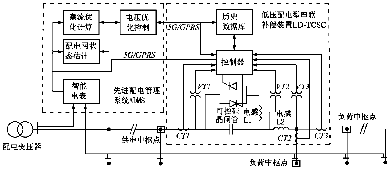
Figure 2 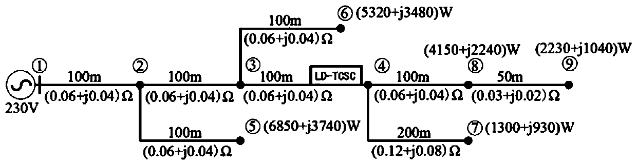
Figure 3
Abstract
Description
technical field
[0001] The invention belongs to the field of power systems, and relates to a thyristor-controlled series compensation control method for a low-voltage distribution network. Background technique
[0002] The low-voltage power distribution network is located at the end of the system. Its grid structure is weak, the line is long, the line path is small, and the load increases rapidly, which often leads to serious voltage drop. In order to solve the low-voltage problem in the low-voltage distribution network, power system engineers usually use adjustment Transformer transformation ratio, strengthen network construction, increase power equipment and other measures. Installing uninterruptible power supply (UPS), static var compensator (SVC) and other power equipment is the most efficient, cheapest and most widely used means of voltage improvement. Frequent switching operations and other problems. In order to solve the problem of concentrated voltage improvement u...
Examples
Embodiment Construction
[0069] Embodiments of the present invention are described below through specific examples, and those skilled in the art can easily understand other advantages and effects of the present invention from the content disclosed in this specification. The present invention can also be implemented or applied through other different specific implementation modes, and various modifications or changes can be made to the details in this specification based on different viewpoints and applications without departing from the spirit of the present invention. It should be noted that the diagrams provided in the following embodiments are only schematically illustrating the basic concept of the present invention, and the following embodiments and the features in the embodiments can be combined with each other in the case of no conflict.
[0070] Wherein, the accompanying drawings are for illustrative purposes only, and represent only schematic diagrams, rather than physical drawings, and should...