
Overhead line system fixing frame cable tensioning device and control alarm system thereof
A technology of tensioning device and fixing frame, which is applied in the power supply field of electrified railway, subway and urban rail transit, and can solve problems such as falling lumps, potential safety hazards of pedestrians in bridges and traffic equipment, and lack of disconnection locking device, etc.
Patent Information
- Authority / Receiving Office
- CN · China
- Current Assignee / Owner
- Publication Date
- 2020-11-10
Smart Images
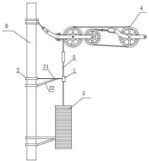
Figure 1 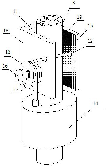
Figure 2 
Figure 3
Abstract
Description
technical field
[0001] The invention relates to the technical field of power supply for electrified railways, subways and urban rail transit, in particular to a cable tensioning device for a catenary fixing frame and a control and alarm system thereof. Background technique
[0002] A catenary is a special form of transmission line assumed to supply power to electric locomotives along railway lines, subway lines, or urban rail lines. The catenary compensation device is to compensate the tension change of the wire in the transmission line to keep the tension constant.
[0003] Existing catenary compensation devices mainly include several types of pulley compensation devices, Bore sheave compensation devices, spring compensation devices, and hydraulic compensation devices.
[0004] The pulley compensation device includes a pulley assembly, a compensation rope, a pestle ring bar, a weight bar, a weight weight and connecting parts for connecting the pulley assembly, a compensati...
Examples
Embodiment 1
[0053] like figure 1 As shown, a catenary fixed frame cable tensioning device is fixed on the electric pole 6 through a pestle ring rod, and includes a pulley compensation device, and the pulley compensation device includes a compensation rope 3, a pulley assembly 4, and a falling lump assembly 5 , the compensation rope 3 goes around the pulley assembly 4 and extends downwards and is connected with the weight drop assembly 5 . The tensioning device also includes a quick locking structure 1 and a fixing frame 2 for fixing the quick locking structure 1 on the electric pole 6, the compensation rope 3 extends downward through the quick locking structure 1 and is connected with the falling tuo assembly 5 connections. When the compensation rope 3 or catenary breaks, the fast locking structure 1 quickly locks the descending compensation rope 3, so that the compensation rope 3 stops rapidly, avoiding falling lumps from falling down, and bringing potential safety hazards to bridges, t...
Embodiment 2
[0055] This embodiment is improved on the basis of Embodiment 1, and its improvements are as follows: figure 2 As shown, the quick locking structure 1 includes a locking rope 12, a reel 13, a locking sleeve 14 and a locking piece 11; the locking piece 11 includes a left locking piece 18 connected as one, a right locking piece piece 19, the left locking piece 18 and the right locking piece 19 are respectively arranged on both sides of the compensation rope 3 and are in contact with the compensation rope 3; the locking sleeve 14 is fixedly set on the compensation rope 3, and the reel 13 is fixedly installed on the locking piece 11, one end of the locking rope 12 is fixedly connected to the locking sleeve 14, and the other end of the locking rope 12 goes around the reel 13 and passes through the left locking piece 18, The right locking piece 19 is fixed on the locking piece 11 ; the locking piece 11 is fixedly connected with the fixing frame 2 . .
[0056] When the compensatio...
Embodiment 3
[0059] This embodiment is improved on the basis of Embodiment 2. The improvement is that: the locking rope 12 is fixedly connected to the locking piece 11 through a tension spring, and the compensation rope is dispersed through the tension spring and the locking piece 11 3, reduce the kinetic energy impact on the locking rope 12, and prevent the locking rope 12 from breaking under the impact of kinetic energy.
[0060] In addition, the locking rope 12 can also be fixedly connected to the locking piece 11 through a tension spring, and the kinetic energy of the compensating rope 3 can be dispersed through the tension spring and the locking piece 11, so as to reduce the kinetic energy impact on the locking rope 12 and avoid locking. Stop rope 12 fractures under the impact of kinetic energy.
[0061] Other parts in this embodiment are basically the same as those in Embodiment 2, so details will not be repeated one by one.