
A kind of multifunctional electric bicycle support
A multi-functional technology for electric bicycles, applied to bicycle brackets, bicycle accessories, steering mechanisms, etc., can solve the problems of occupying limited space, shaking arms all the time, and difficulty passing through, so as to reduce the space occupied by parking and increase the parking speed , the effect of parking neatly
Patent Information
- Authority / Receiving Office
- CN · China
- Patent Type
- Patents(China)
- Current Assignee / Owner
- Publication Date
- 2021-12-28
Smart Images
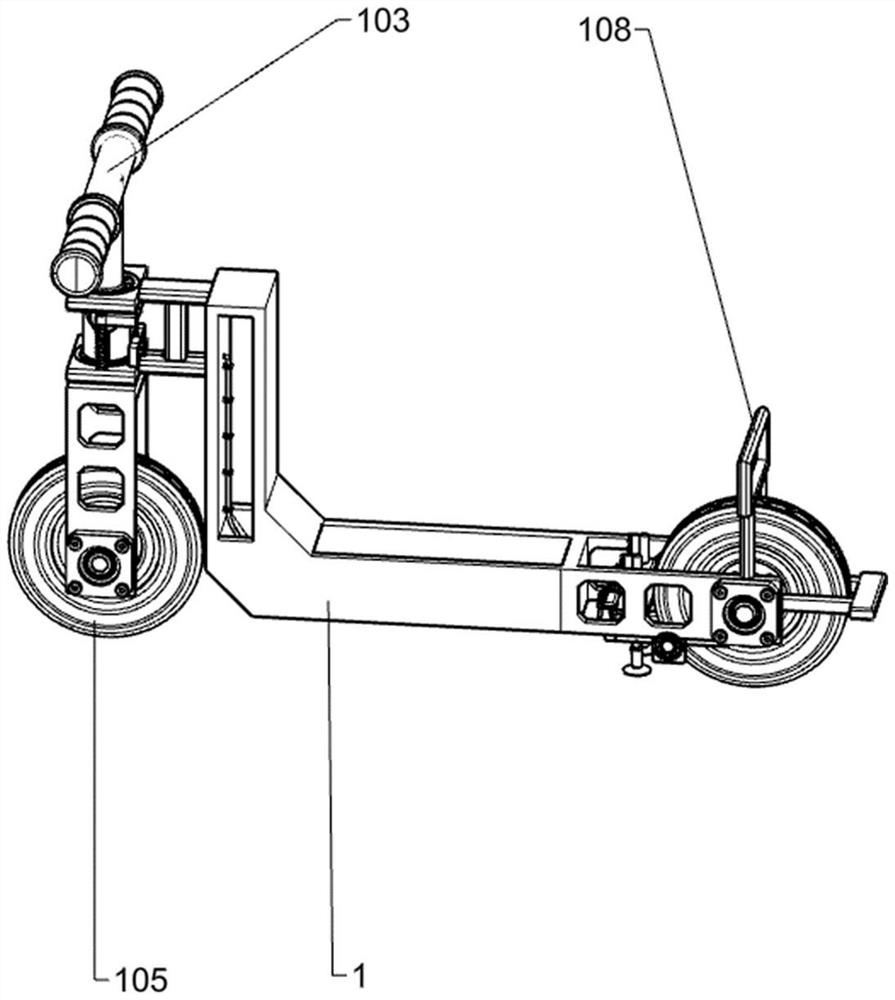
Figure 1 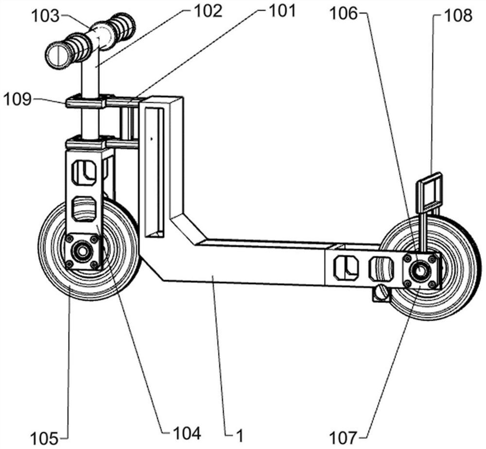
Figure 2 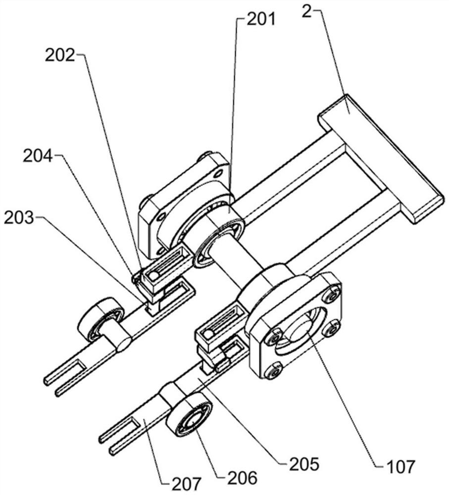
Figure 3
Abstract
Description
technical field
[0001] The invention relates to an electric bicycle support, in particular to a multifunctional electric bicycle support. Background technique
[0002] Nowadays, people often use bicycles or electric vehicles to travel, which is also the healthiest way of travel. Cycling not only protects the environment, but also exercises the body, which is very in line with the current trend. However, with the increase in the number of bicycles, the bicycle Placement became a big problem.
[0003] When existing bicycles or electric vehicles are parked and placed, one is to park the car with an inclined rear support, and the other is to support the wheels to park the car with the rear support, and the front wheels of the parked bicycle or electric vehicle are in an inclined state. , The front wheels in the tilted state take up a lot of space and are not suitable for batch parking, causing tight parking spaces for urban parking spaces.
[0004] Aiming at the problems menti...
Examples
Embodiment 1
[0066] A multifunctional electric bicycle stand, such as Figure 1-8 Shown, include vehicle frame 1, I-shaped frame 101, support plate 109, rotating bar 102, handlebar 103, support frame 104, wheel 105, first axle rod 106, bearing seat 107, support frame 108, back support mechanism , the control mechanism and the straightening mechanism, the I-shaped frame 101 is affixed to the left upper end of the vehicle frame 1, two support plates 109 are affixed to the left side of the I-shaped frame 101, and the rotating rod 102 is rotatably installed in the middle of the support plate 109 position, the rotating rod 102 runs through two supporting plates 109, the handlebar 103 is fixedly connected to the upper end of the rotating rod 102, the supporting frame 104 is fixedly installed on the lower end of the rotating rod 102, and the supporting frame 104 is located at the lower side of the supporting plate 109 at the lower position, There are two first shaft rods 106, the first shaft rod ...
Embodiment 2
[0069] On the basis of Example 1, such as Figure 3-4 As shown, the back support mechanism includes a first bearing 201, a press frame 2, a slide plate 202, a sliding column one 203, a parallel block 204, a second bearing 206, a connecting plate one 205, a connecting plate two 207, a supporting block one 3, a support Rod 1 301, support plate 301a, rack 302, fixed pin 303, connecting plate 3 304, extension spring 305, support block 2 306, fixed block 1 307, third bearing 309, second shaft 310, elbow 308, Wire rope 308a, spur gear 311, fixed frame 312 and torsion spring 313, two first bearings 201 are installed on the front and rear ends of the first axle bar 106 that is positioned at the right end of the vehicle frame, and press frame 2 is fixedly installed on the right side of the first bearing 201. side, two slide plates 202 are respectively fixedly installed on the left side of the two first bearings 201, the upper end of the slide column 203 is slidingly connected with the ...
Embodiment 3
[0072] On the basis of Example 2, such as Figure 5-6 As shown, the control mechanism includes a fixed block 2 314a, a pressure rod 314, a spring 314b and a clamp 315, the four fixed blocks 314a are fixedly installed on the left side of the support block 1 3, and the pressure rod 314 is slidably installed on the fixed block 2 In 314a, the pressing rod 314 runs through the fixing block 2 314a, the upper ends of the four springs 1 314b are connected to the pressing rod 314, the lower ends of the spring 1 314b are connected to the fixing block 2 314a, and the two clamping plates 315 are fixedly mounted on the front and rear ends of the pressing rod 314 , the clamping plate 315 is located between two adjacent fixing blocks 2 314a, and the clamping plate 315 cooperates with the fixing block 2 314a.
[0073] When the handlebar 103 does not need to be fixed, the manpower presses the pressure bar 314 downwards. At this time, the spring one 314b is compressed, and the clamping plate 31...