
Bird repelling device for high-voltage electric tower by utilizing wind power to produce sound
A high-voltage electricity and wind power technology, applied in the field of bird repelling devices, can solve the problems of safety hazards and poor bird repelling effect, and achieve the effect of no safety hazards and not easy to be affected by the external environment
Patent Information
- Authority / Receiving Office
- CN · China
- Patent Type
- Applications(China)
- Current Assignee / Owner
- Publication Date
- 2021-03-12
- Estimated Expiration
- Not applicable · inactive patent
Smart Images
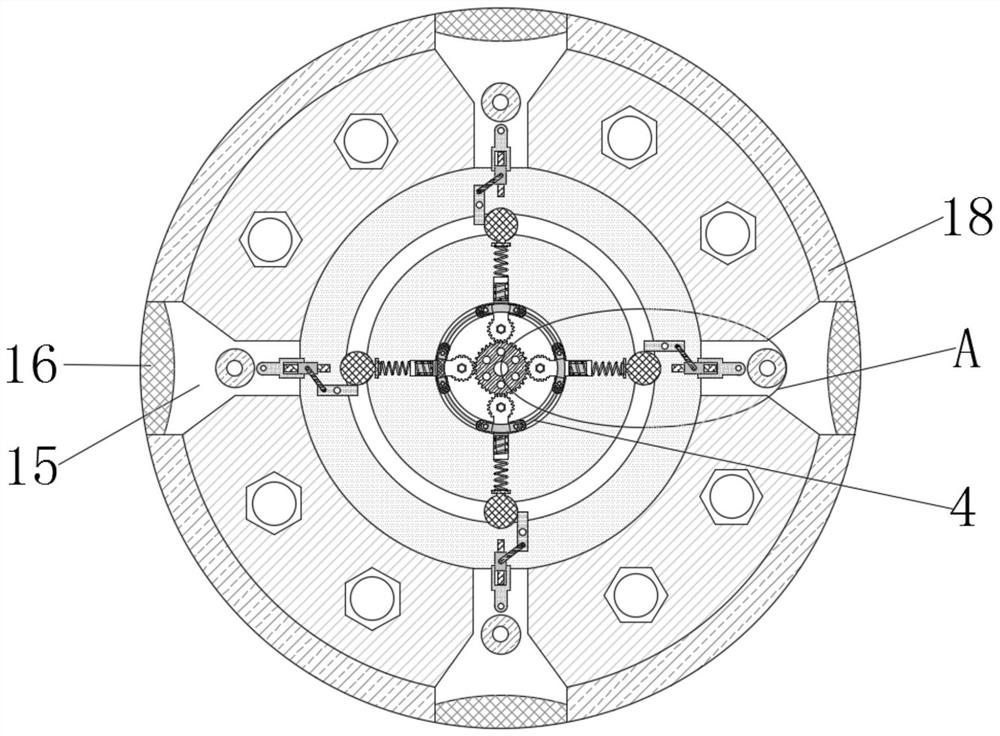
Figure 1 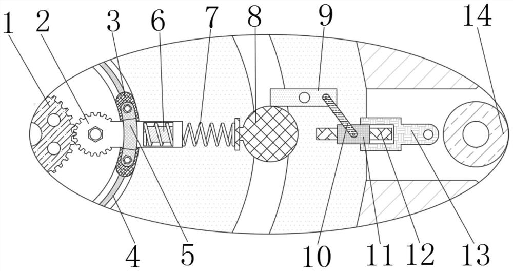
Figure 2 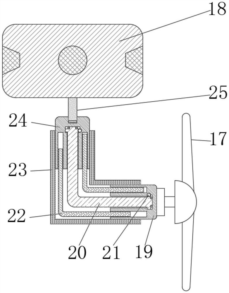
Figure 3
Abstract
Description
technical field
[0001] The invention relates to the technical field of bird repelling devices, in particular to a bird repelling device used for high-voltage electric towers to generate sound by wind force. Background technique
[0002] In recent years, with the development of society, my country's power grid construction has become more and more extensive, and most of my country's power transmission overhead lines are built in the wild, and it is not easy to be monitored by manpower in time. Therefore, it is greatly affected by bird activities, and people's awareness of environmental protection With the enhancement of the environment and the continuous improvement of the ecological environment, the awareness of bird protection is getting stronger and stronger. Therefore, in order to prevent the high-voltage electric tower from being affected by birds, a bird repellent device for electric towers was invented and designed.
[0003] The current high-voltage electric tower bird ...
Examples
Embodiment Construction
[0023] The following will clearly and completely describe the technical solutions in the embodiments of the present invention with reference to the accompanying drawings in the embodiments of the present invention. Obviously, the described embodiments are only some, not all, embodiments of the present invention. Based on the embodiments of the present invention, all other embodiments obtained by persons of ordinary skill in the art without making creative efforts belong to the protection scope of the present invention.
[0024] see Figure 1-3 , a bird-repelling device used for high-voltage electric towers to make sound by wind, including a central gear 1, a rotating body 2 is slidably installed on the right end of the central gear 1, and a sliding block 3 is slidably installed below the rotating body 2, and the sliding block 3 The track 4 is fixedly installed at the bottom, and the fixing clip 5 is fixedly installed above the sliding block 3. The fixing clip 5 is fixed on the...