
Bamboo surface peeling equipment
A kind of equipment, bamboo technology, applied in the field of bamboo surface peeling equipment, can solve the problems of manpower consumption, low efficiency, bamboo peeling deviation, etc., and achieve the effect of saving manpower, convenient collection and cleaning, and convenient cleaning
Patent Information
- Authority / Receiving Office
- CN · China
- Patent Type
- Applications(China)
- Current Assignee / Owner
- Publication Date
- 2021-06-18
Smart Images
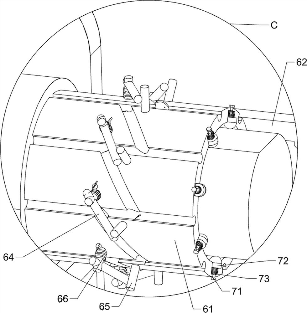
Figure 1 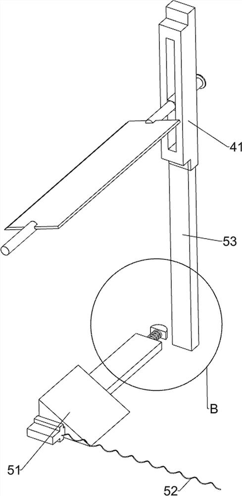
Figure 2 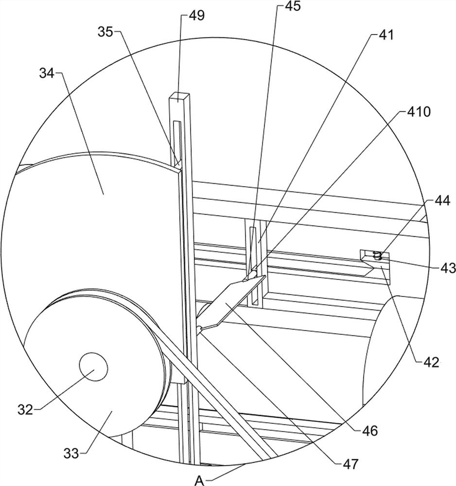
Figure 3
Abstract
Description
technical field
[0001] The invention relates to a peeling device, in particular to a bamboo surface peeling device. Background technique
[0002] Bamboo is tall and slender, green all the year round, and has always been loved by Chinese people. In addition to its high ornamental value, bamboo is also a high-quality raw material in handicrafts and other fields. Sometimes in order to make certain handicraft items, its skin needs to be removed. Bare bamboo that is smooth and flat without bark.
[0003] The traditional bamboo surface peeling technology is to manually move the bamboo to a suitable position, hold a cutter, manually scrape off the skin, and rotate the bamboo during the scraping process to ensure that the bamboo skin is completely removed. , firstly scrape the skin manually, which is labor-intensive and easy to hurt hands, and secondly, the scraped skin falls on the ground, which is difficult to collect and clean up, while manually rotating the bamboo is very troub...
Examples
Embodiment 1
[0030] A kind of bamboo surface peeling equipment, such as figure 1 , figure 2 with image 3 As shown, it includes a base 1, a support frame 2, a power mechanism 3 and a cutting mechanism 4. The upper part of the base 1 is connected with a support frame 2, and a power mechanism 3 is arranged between the right side of the upper part of the base 1 and the front side of the upper part of the support frame 2 to support A cutting mechanism 4 is arranged between the top of the frame 2 and the power mechanism 3 .
[0031] Power mechanism 3 comprises motor 31, rotating shaft 32, transmission group 33, rotating disk 34 and first connecting rod 35, and base 1 top right side is equipped with motor 31, and bracing frame 2 top right front side is connected with rotating shaft 32 in a rotational manner, and rotates A transmission group 33 is connected between the front side of the shaft 32 and the front side of the output shaft of the motor 31 , the rear side of the rotating shaft 32 is ...
Embodiment 2
[0035] On the basis of Example 1, such as figure 1 , figure 2 , Figure 4 , Figure 5 , Image 6 , Figure 7 with Figure 8 As shown, the pusher assembly 5 is also included, and the pusher assembly 5 includes a special-shaped slide bar 51, a second spring 52, a fifth connecting rod 53, a sixth connecting rod 54, a second wedge block 55 and a third spring 56, A special-shaped slide bar 51 is slidably connected between the front and rear sides of the receiving trough 48, a second spring 52 is connected between the right side of the front part of the special-shaped slide bar 51 and the receiving chute, and the rear side of the special-shaped slide bar 51 is slidably connected with The sixth connecting rod 54, the second wedge block 55 is connected to the rear side of the sixth connecting rod 54, the third spring 56 is connected between the second wedge block 55 and the special-shaped slide bar 51, and the third spring 56 is sleeved on the sixth connecting rod 54 , the lowe...