
Charge pump with wide locking range and low current mismatch
A locking range, charge pump technology, applied in the field of microelectronics, can solve the problems of restricting charge pump application, charge sharing, current mismatch, etc.
Patent Information
- Authority / Receiving Office
- CN · China
- Current Assignee / Owner
- Publication Date
- 2021-04-13
Smart Images
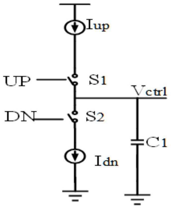
Figure 1 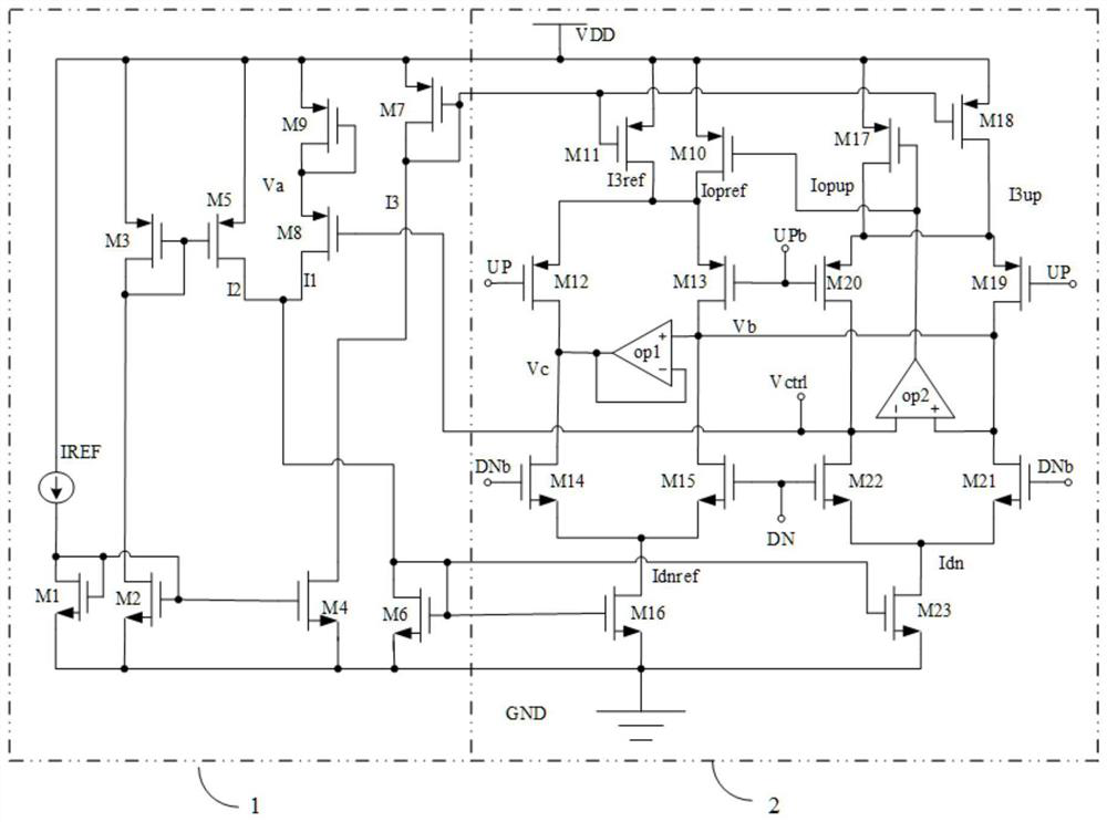
Figure 2 
Figure 3
Abstract
Description
technical field
[0001] The invention belongs to the technical field of microelectronics, and in particular relates to a charge pump with a wide locking range and low current mismatch. Background technique
[0002] The charge pump is an important functional module of the delay-locked loop, and its performance directly affects the overall performance of the delay-locked loop. figure 1 As a basic charge pump structure, when the switch S1 is closed and S2 is open, the charging current source I UP When the capacitor C1 is charged, the voltage at the output terminal VCtrl of the charge pump rises; when the switch S1 is disconnected and S2 is closed, the discharge current source I DN When the capacitor C1 is discharged, the voltage at the output terminal VCtrl of the charge pump drops; when the switch S1 and the switch S2 are turned on or off at the same time, the voltage at the output terminal VCtrl of the charge pump remains unchanged. figure 1 The traditional charge pump shown...
Examples
Embodiment
[0021] A wide lock range low current mismatch charge pump such as figure 2 As shown, including charge pump bias circuit 1, charge pump core circuit 2;
[0022] Wherein, the signal output terminal of the charge pump bias circuit 1 is connected to the signal input terminal of the charge pump core circuit 2, and the signal output terminal of the charge pump core circuit 2 is connected to the signal input of the charge pump bias circuit 1 terminal; the charge pump bias circuit 1 provides a bias signal for the charge pump core circuit 2, and the charge pump core circuit 2 provides charge / discharge current for the filter capacitor of the subsequent stage circuit.
[0023] As a preferred technical solution, such as figure 2 As shown, the charge pump bias circuit 1 includes: reference current source IREF, NMOS transistor M1, NMOS transistor M2, PMOS transistor M3, NMOS transistor M4, PMOS transistor M5, NMOS transistor M6, PMOS transistor M7, PMOS transistor M8 and PMOS transistor...