
High-precision voltage-time converter
A converter, high-precision technology, applied in the field of high-precision voltage-time converters, can solve the problem of low VTC conversion accuracy, and achieve the effect of improving conversion accuracy, reducing comparison error, and constant threshold voltage
Patent Information
- Authority / Receiving Office
- CN · China
- Patent Type
- Applications(China)
- Current Assignee / Owner
- Publication Date
- 2021-11-02
Smart Images
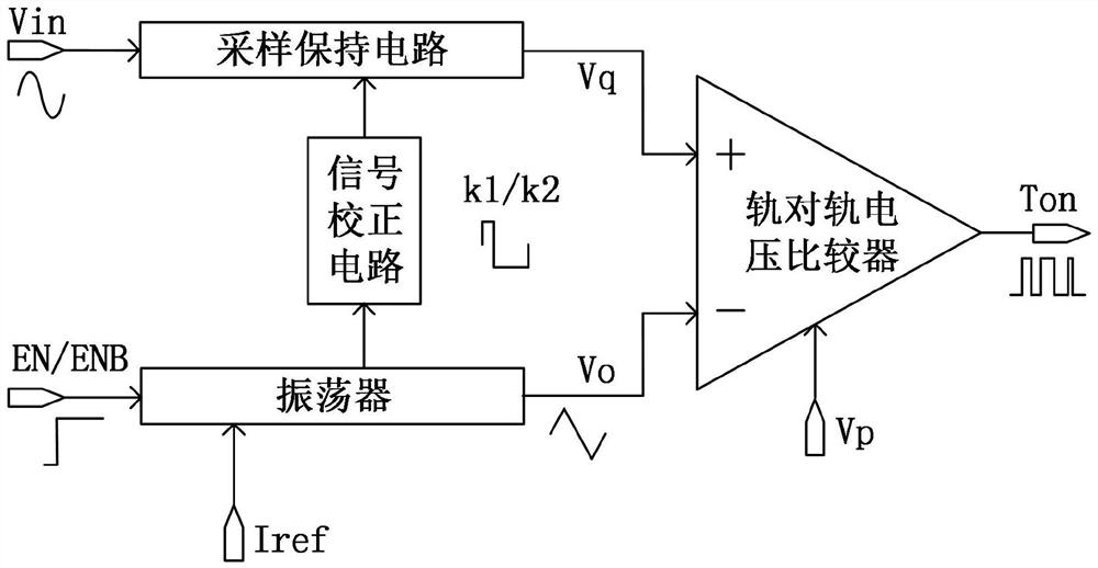
Figure 1 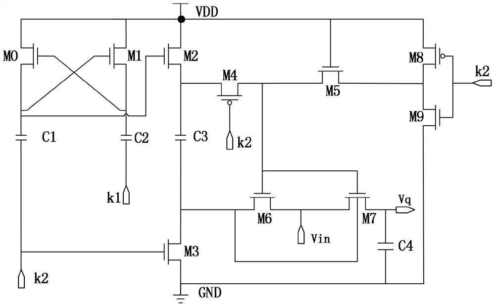
Figure 2 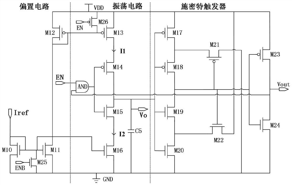
Figure 3
Abstract
Description
technical field
[0001] The invention belongs to the field of time-domain ADC integrated circuit design, in particular to a high-precision voltage-time converter (VTC) for converting voltage signals into time signals. Background technique
[0002] With the progress of the semiconductor process, non-ideal factors such as thermal noise in the analog circuit have not improved with the improvement of the process, and the gain bandwidth and linearity of the operational amplifier in the analog circuit have also weakened. In view of factors such as the limited performance of voltage-domain ADCs during the continuous improvement of semiconductor technology, time-domain ADCs have the advantages of high resolution, small area, simple structure, and low power consumption. As an important part of time-domain ADC, VTC converts continuous voltage signals into time signals. Its conversion accuracy determines the quantization accuracy of time-domain ADC. VTC has become the focus of current r...
Examples
Embodiment Construction
[0070] In this example, if figure 1 As shown, a high-precision voltage-time converter structure, including:
[0071] A sample-and-hold circuit used to realize input voltage sampling, which can ensure accurate sampling of the input voltage signal and store it in the sampling capacitor, and hold the input voltage signal during the quantization of the comparator. The structure uses a gate voltage bootstrap switch Reduce the non-linearity of MOS on-resistance;
[0072] An oscillator for generating a triangular wave signal Vo and a rectangular wave signal Vout, the circuit adopts the generated triangular wave signal Vo for comparison with the sampling voltage signal Vq, and the square wave signal Vout generated by the circuit is used as the input signal of the signal correction circuit;
[0073] A signal correction circuit for generating the logic control signal k1 / k2, which can adjust the duty cycle of the input square wave signal and correct the phase relationship between the lo...