
Clamp apparatus
a technology of clamping and clamping rods, which is applied in the direction of clamps, manufacturing tools, and vices, etc., can solve the problems of affecting the rotational operation of the clamping rods, affecting the removal of spatter, so as to achieve the elimination of spatter, easy and reliable removal, and short time
Patent Information
- Authority / Receiving Office
- US · United States
- Patent Type
- Patents(United States)
- Current Assignee / Owner
- Publication Date
- 2019-07-02
Smart Images
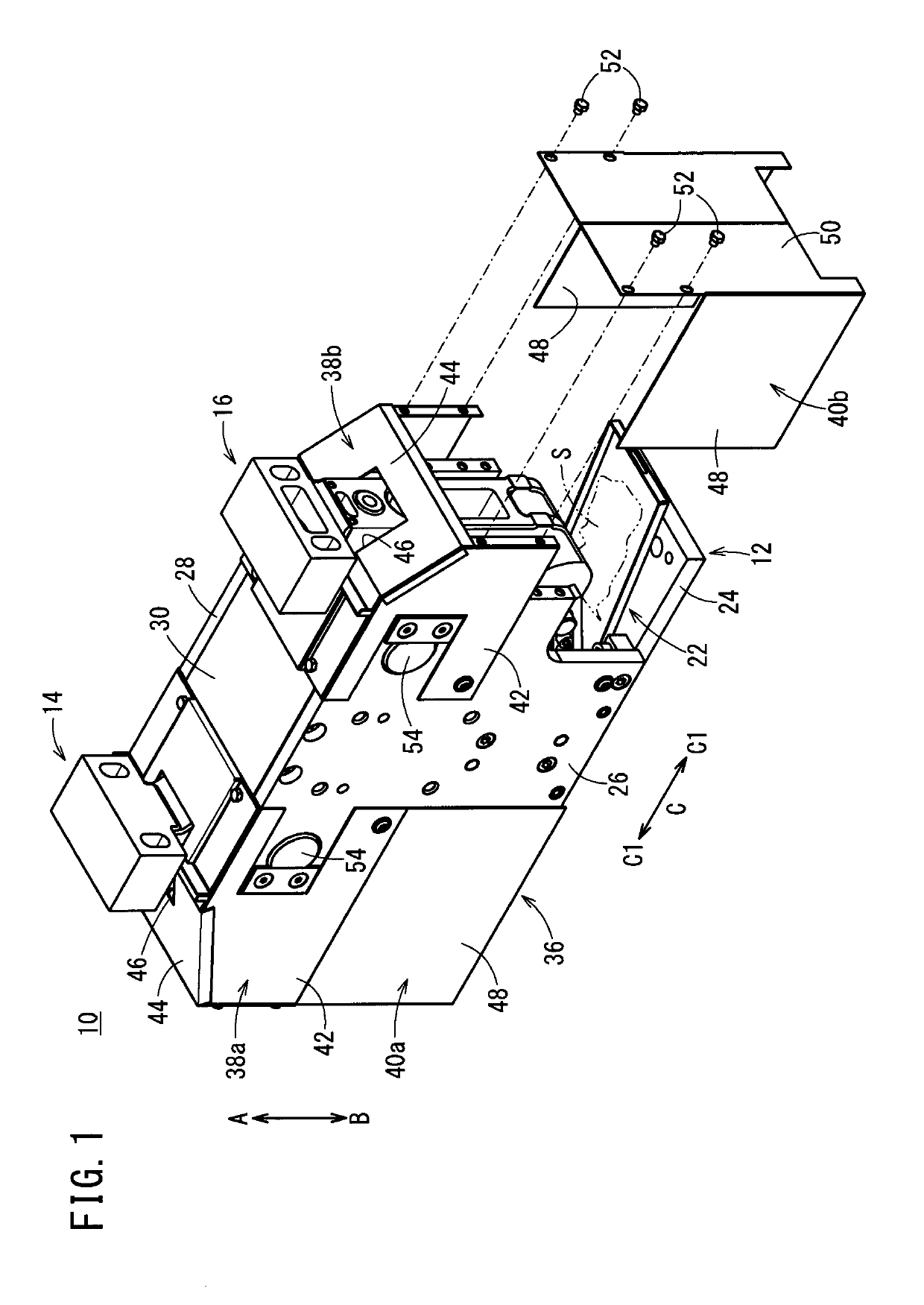
Figure 1 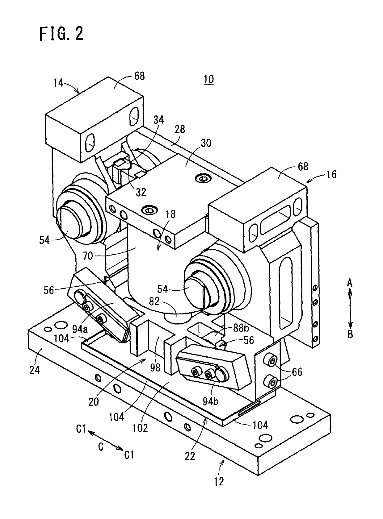
Figure 2 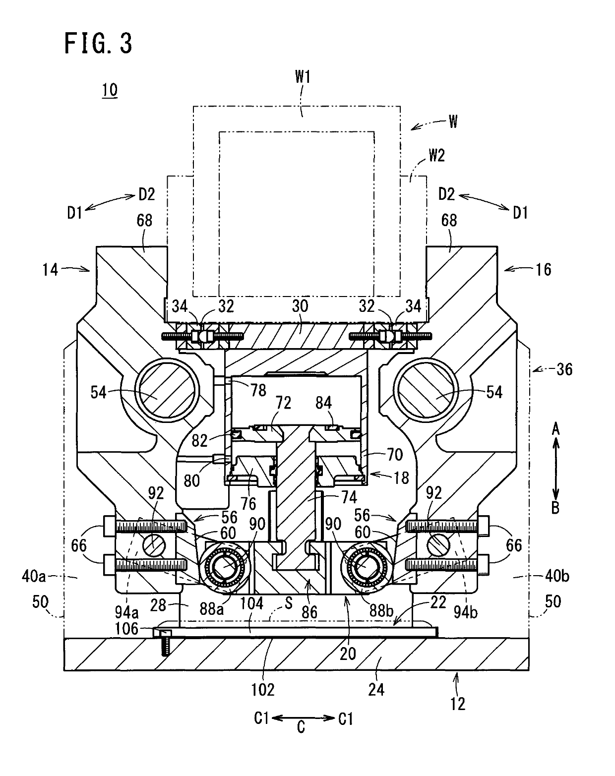
Figure 3
Abstract
Description
TECHNICAL FIELD
[0001] The present invention relates to a clamp apparatus for clamping workpieces on an automated assembly line or the like.BACKGROUND ART
[0002] Heretofore, in an automated assembly line for automobiles, an assembly process has been performed in which clamping is carried out by a clamp apparatus under a condition in which pre-formed frames are positioned in an overlaid manner and the frames are welded together.
[0003] In one such clamp apparatus, as disclosed in Japanese Patent No. 4950123, left and right clamp arms are provided as a pair, the clamp arms being disposed for rotation respectively through pins. Further, proximal ends of the clamp arms are supported pivotally by a base to which a drive unit in the form of an air cylinder is connected, whereby distal ends of the clamp arms are operated to open and close. Thus, a workpiece such as a frame or the like is gripped from the left and right by the distal ends of the pair of clamp arms.SUMMARY OF THE INVENTION
[0004] Wi...
Examples
first embodiment
[0056]The clamp apparatus 10 according to the present invention is constructed basically as described above. Next, operations and advantages of the clamp apparatus 10 will be explained. In the following description, the unclamped condition, in which the gripping members 68 of the first and second clamp arms 14, 16 are separated mutually from each other, will be described as an initial position. In the initial position, pressure fluid is supplied to the second port 80, and a state is assumed in which the piston 72 is raised, whereby the first and second clamp arms 14, 16 are rotated, via the block body 86 and the link arms 94a, 94b of the driving force transmission mechanism 20, about the arm pins 54 in directions (the directions of the arrows D1) so that the gripping members 68 are separated away from each other.
[0057]At first, in a state in which a workpiece W is placed on the ceiling portion 30, under a switching action of a non-illustrated switching device, the pressure fluid, wh...
second embodiment
[0075]In the clamp apparatus 150 the unloading tray 22 is disposed inside the cover 36, at a position below the first and second clamp arms 14, 16 in the direction of gravity (the direction of the arrow B). Thus, during a welding operation on the clamped workpiece W, spatter S, which passes through the openings 46 of the cover 36 and invades into the interior, is suitably received by the unloading tray 22 and can be taken out to the exterior and eliminated easily and reliably through the unloading tray 22. In other words, the operation to remove and eliminate spatter can be preformed easily, and maintainability of the camp apparatus 150 can be enhanced.
[0076]Irrespective of the structures of the driving force transmission mechanisms 20, 152 in the clamp apparatus 10, 150 according to the first and second embodiments, by providing the unloading tray 22 in the interior of the clamp apparatus, the removal operation for eliminating spatter S that has invaded into the apparatus can be p...