

Fence tape
Patent Information
- Authority / Receiving Office
- US · United States
- Current Assignee / Owner
- Publication Date
- 2005-03-03
Smart Images
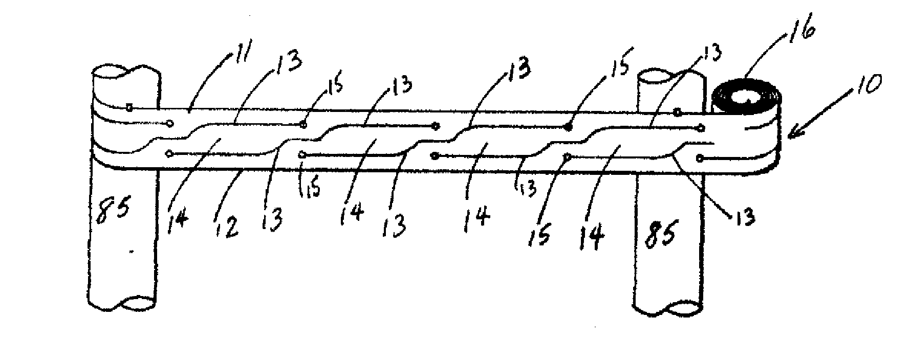
Figure 1 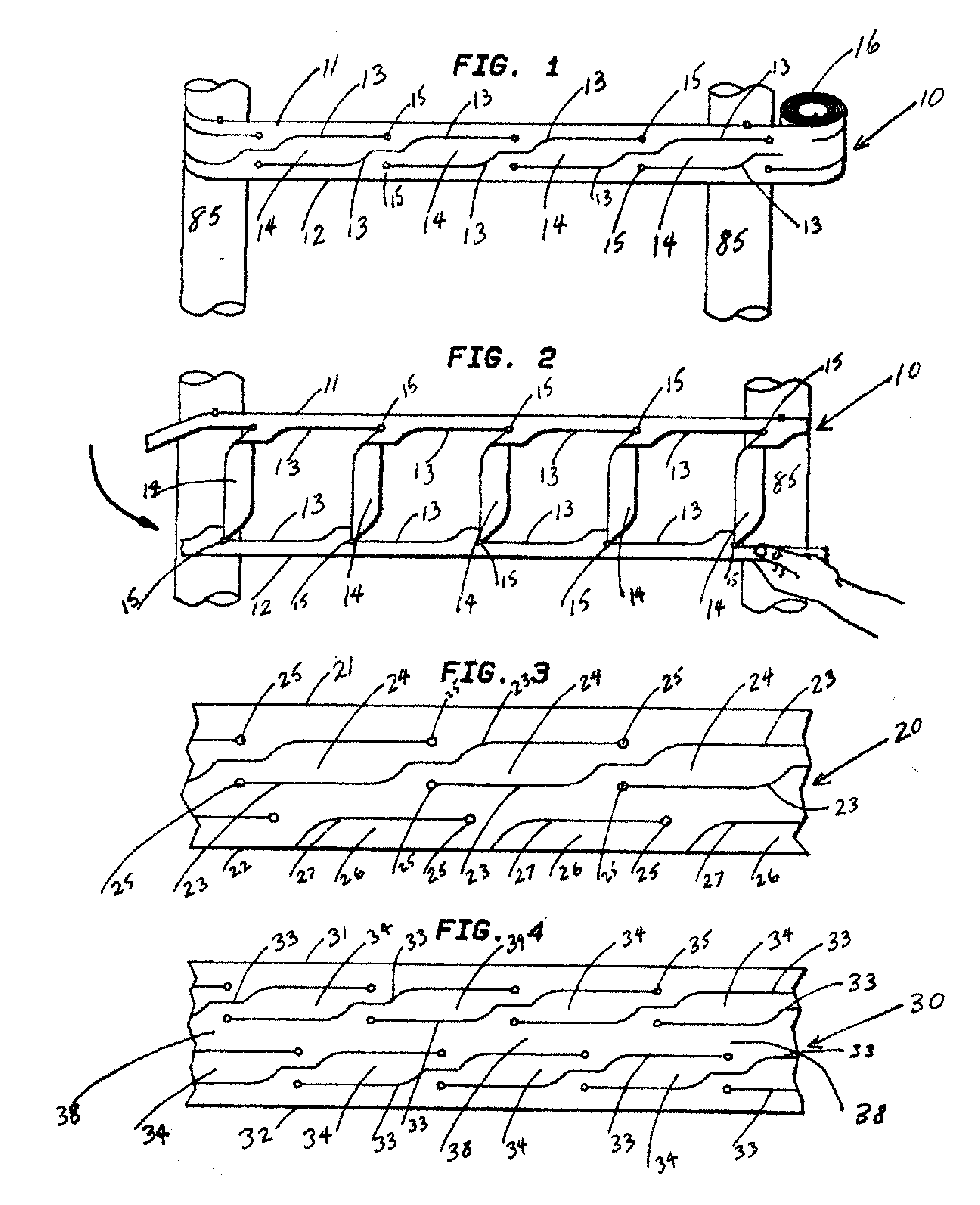
Figure 2 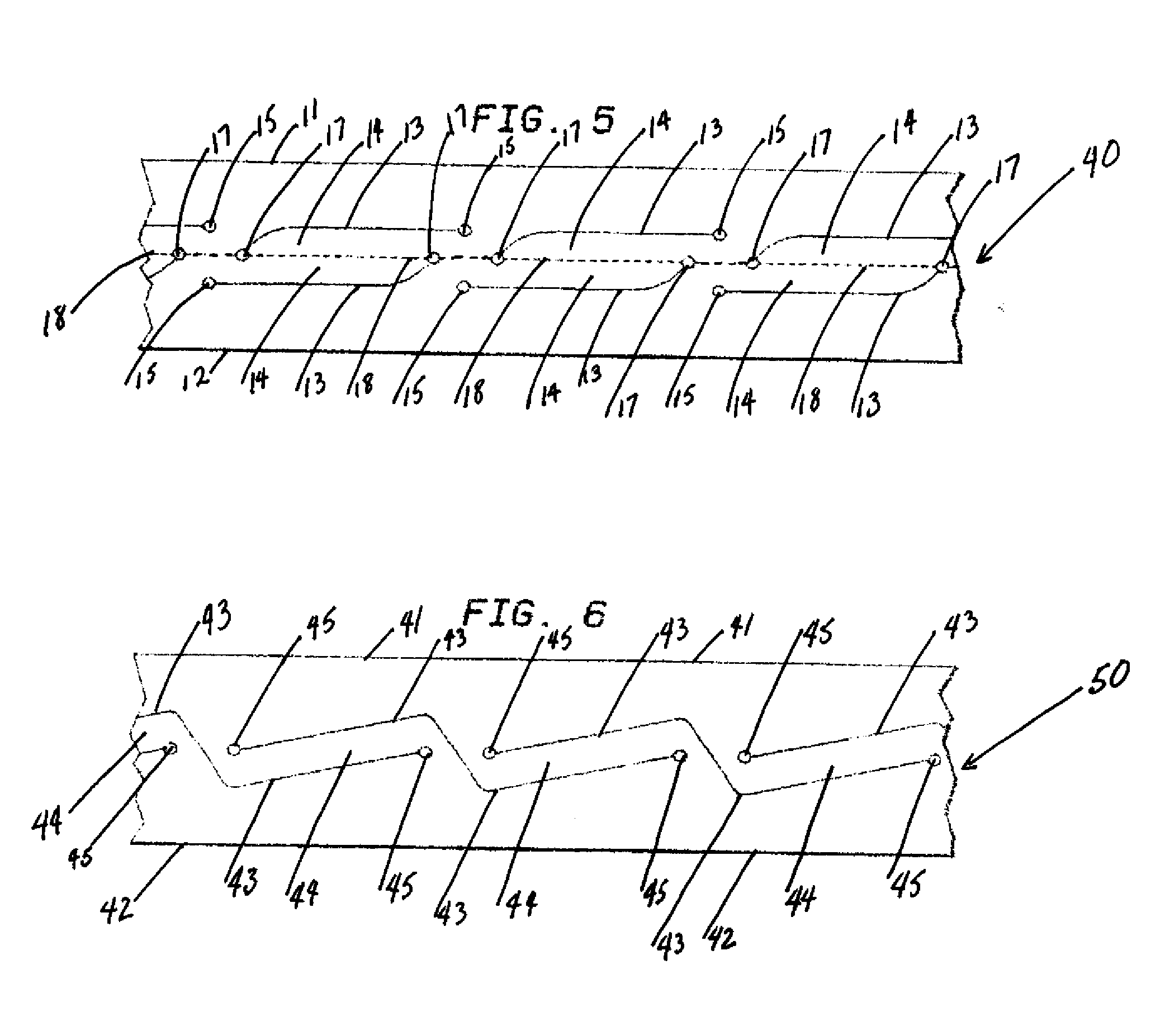
Figure 3
Abstract
Description
CROSS REFERENCE TO RELATED APPLICATIONS
[0001] The present invention is related to my U.S. Pat. No. 5,244,715, entitled FLAG STRIP, the complete text of which is incorporated in its entirety by reference herein. Much of this material was disclosed in U.S. Provisional Patent Application No. 60 / 083,183, entitled FENCE TAPE, filed Apr. 27, 1998, now abandoned, and in its U.S. Non-Provisional counterpart application No. 09 / 300,771, entitled FENCE TAPE, also now abandoned. The complete text of said provisional and non-provisional applications are also incorporated in their entireties by reference herein.BACKGROUND OF INVENTION
[0002] 1. Field of the Invention
[0003] The present invention is an improvement over ribbons or strips used to mark off work or hazardous areas. More specifically the present invention provides for a fence type barrier to be formed by portions of the ribbon or strip.
[0004] 2. Summary of the Prior Art
[0005] Tapes, ribbons or strips, usually of highly flexible resi...
Examples
Embodiment Construction
[0016] The invention is comprised of a flexible web material, typically of plastic such as polyethylene or vinyl, which is slit or die cut to allow the material to be deformed into a fencelike structure.
[0017]FIG. 1 shows the converted flexible web material 10 having a top edge 11 and bottom edge 12 with internal die cuts 13 defining undeployed cross members 14. Punched holes 15 act against stress concentration at the ends of the die cuts. Material 10 is attached, preferably by tying, although any means of attachment such as staples or tape may be used, to preferably vertical posts 85. The unused portion of the material 10, still rolled, is shown as 16.
[0018]FIG. 2 shows the converted flexible web material 10 attached to posts 85 at the top edge 11. The bottom edge 12 is pulled to the right and downward, causing die cuts 13 to open so that cross members 14 are deployed generally vertically to result in a fence like structure.
[0019] The embodiment of FIG. 3 works similarly to that...