
Paper-back tape dispenser
a tape dispenser and paper back technology, applied in the field of paper back tape dispensers, can solve the problems of excessive waste, difficult back insulation, time-consuming,
Patent Information
- Authority / Receiving Office
- US · United States
- Patent Type
- Applications(United States)
- Current Assignee / Owner
- Publication Date
- 2005-06-23
Smart Images
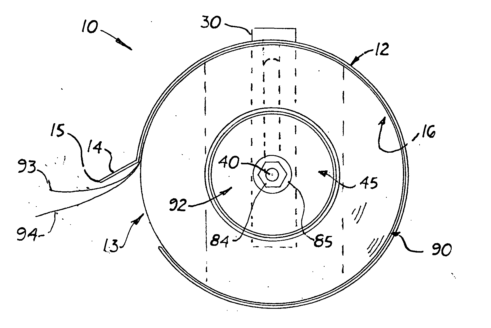
Figure 1 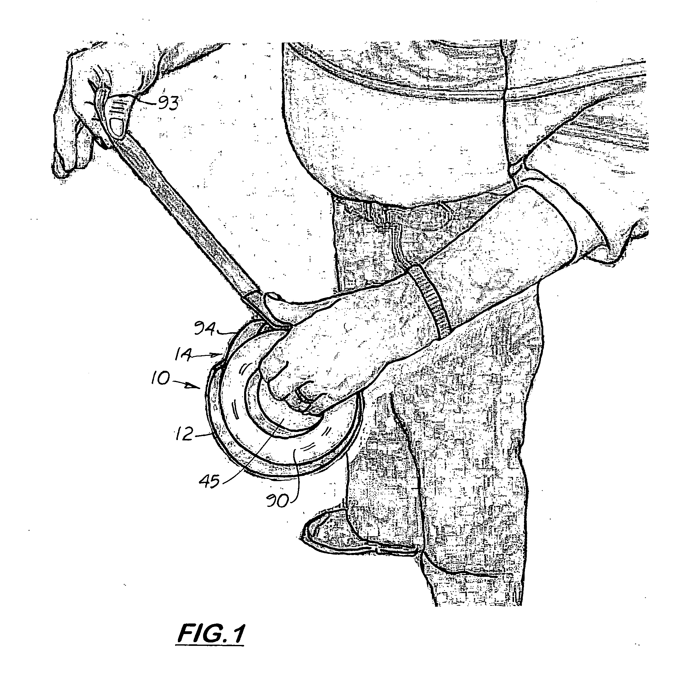
Figure 2 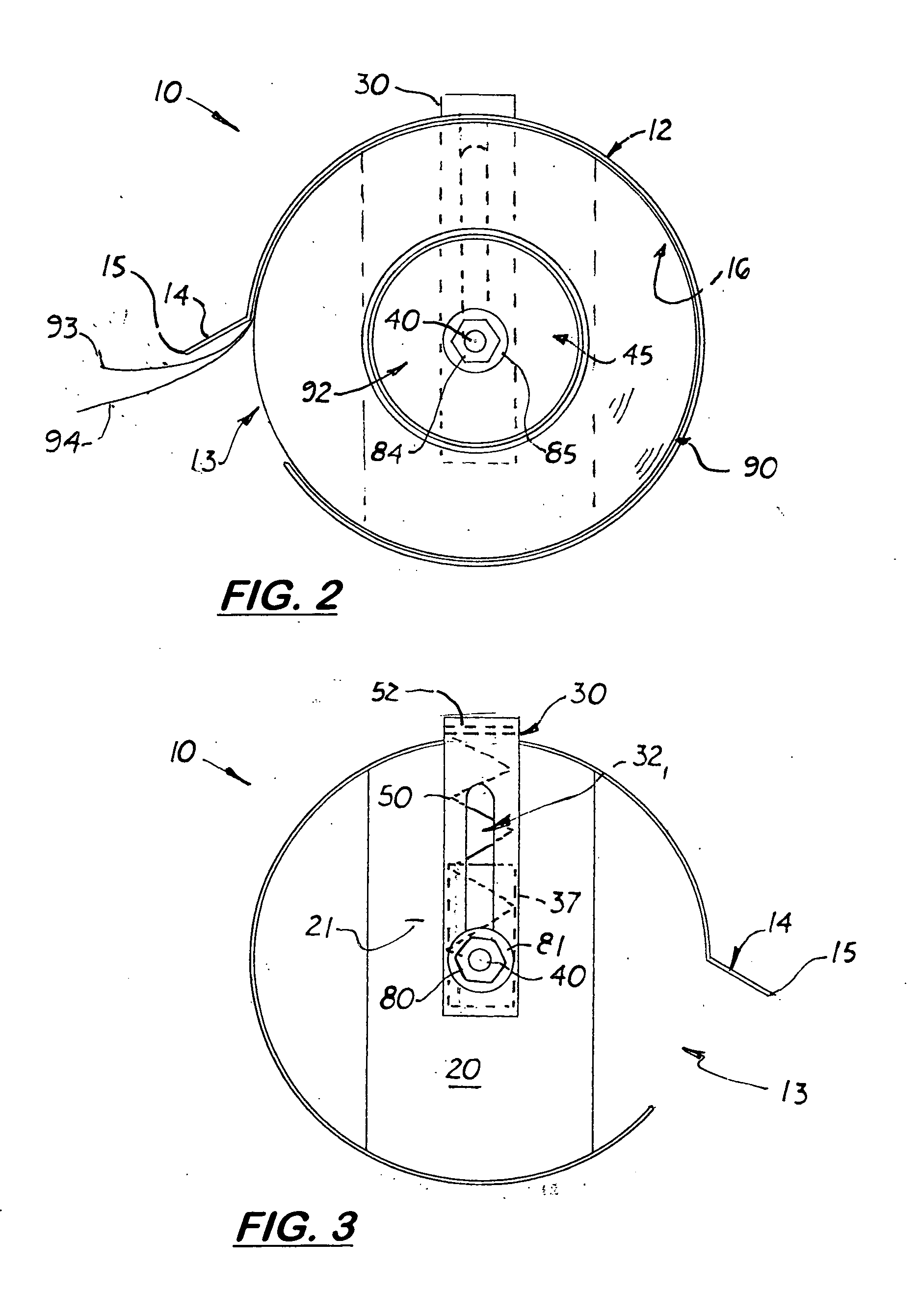
Figure 3
Abstract
Description
BACKGROUND OF THE INVENTION
[0001] This Utility Patent Application is based on Provisonal Patent Application (Ser. No. 60 / 531,267) filed Dec. 22, 2003.
[0002] 1. Field of the Invention
[0003] This invention relates to tape dispensers, and more particularly, to tape dispensers used with adhesive tape that uses a paper layer that is removed prior to application.
[0004] 2. Description of the Related Art
[0005] There are three types of paper back tapes commonly used in the HVAC industry. The first one is a vinyl tape product made by Nashua Corporation of Nashua, N.H. (Product No. NAS-8223). The second is a foil packed tape product also sold by Nashua Corporation (Product No. NAS-323). A third is a reinforced packed tape product also sold by Nashua Corporation (Product No. NAS-FSK-3). All three types of tape are approximately 3 inches in width and distributed in rolls approximately 6 inches in diameter. Typically approximately 30 yards of tape are rolled onto a center spool approximately...
Examples
Embodiment Construction
)
[0020] Referring to the Figs., there is shown a paper back tape dispenser, 10 that includes a a cylindrical outer shell 12 made of sheet metal attached to an optional, transversely aligned back plate 20. Formed on one side of the outer shell 12 is a side opening 13 with a forward extending lip 14 with a distal serrated cutting edge 15 formed thereon. The back plate 20 is securely attached to the back edge of the outer shell 12 thereby forming a cylindrical cavity 16 inside the outer shell 12 capable of receiving a roll of tape 90.
[0021] Longitudinally aligned and attached to the rear surface 21 of the back plate 20 is a hollow short pipe 30. Formed on the inside and outside surfaces of the short pipe 30 are two longitudinally aligned slots 32, 34. Located inside the short pipe 30 is a cylindrical shaped sliding piston 37. The sliding piston 37 is hollow and opened at its opposite ends and slightly smaller in diameter than the pipe 30. During operation, the piston 37 slides freely ...