
Plastic molding die
Patent Information
- Authority / Receiving Office
- US · United States
- Current Assignee / Owner
- Publication Date
- 2006-07-20
- Estimated Expiration
- Not applicable · inactive patent
Smart Images
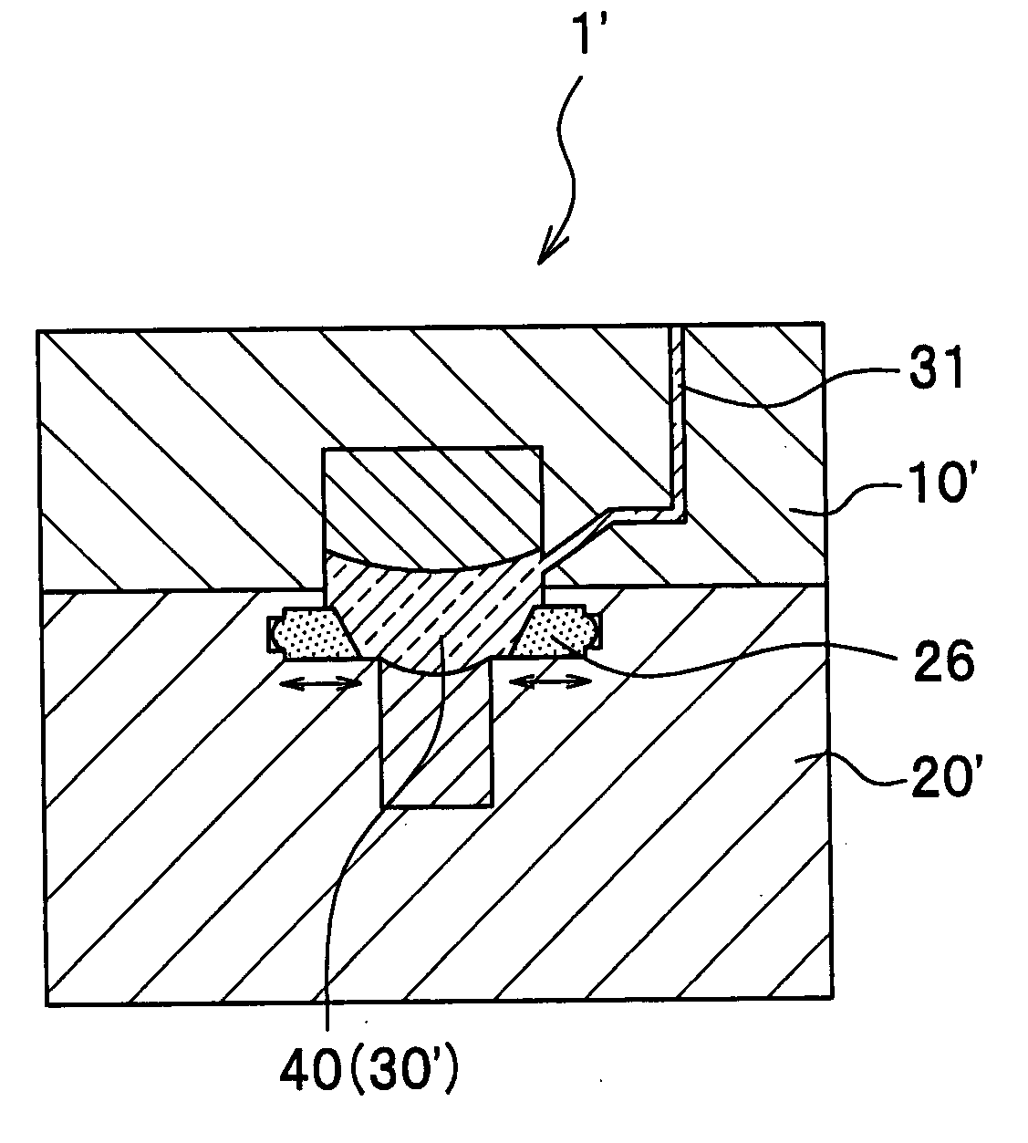
Figure 1 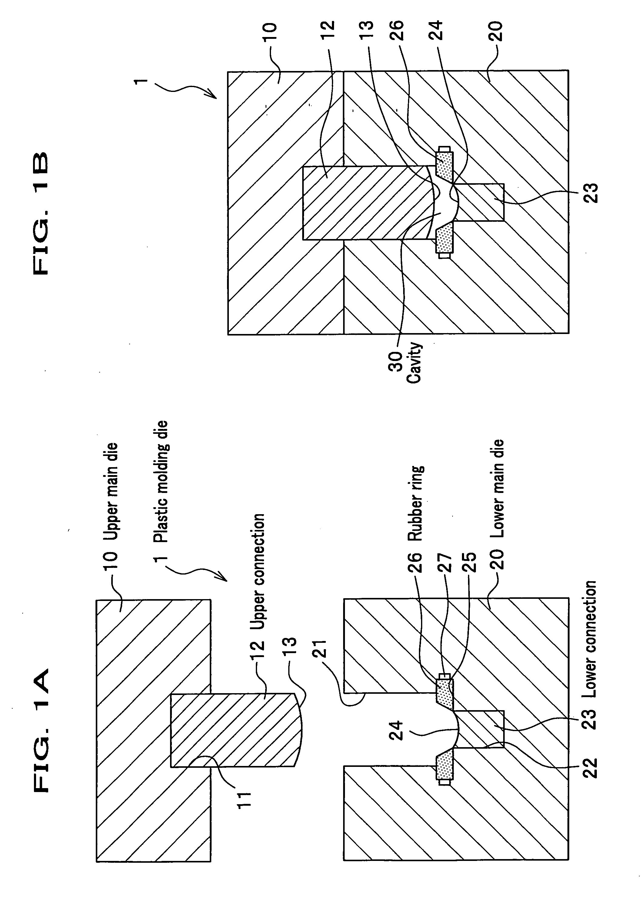
Figure 2 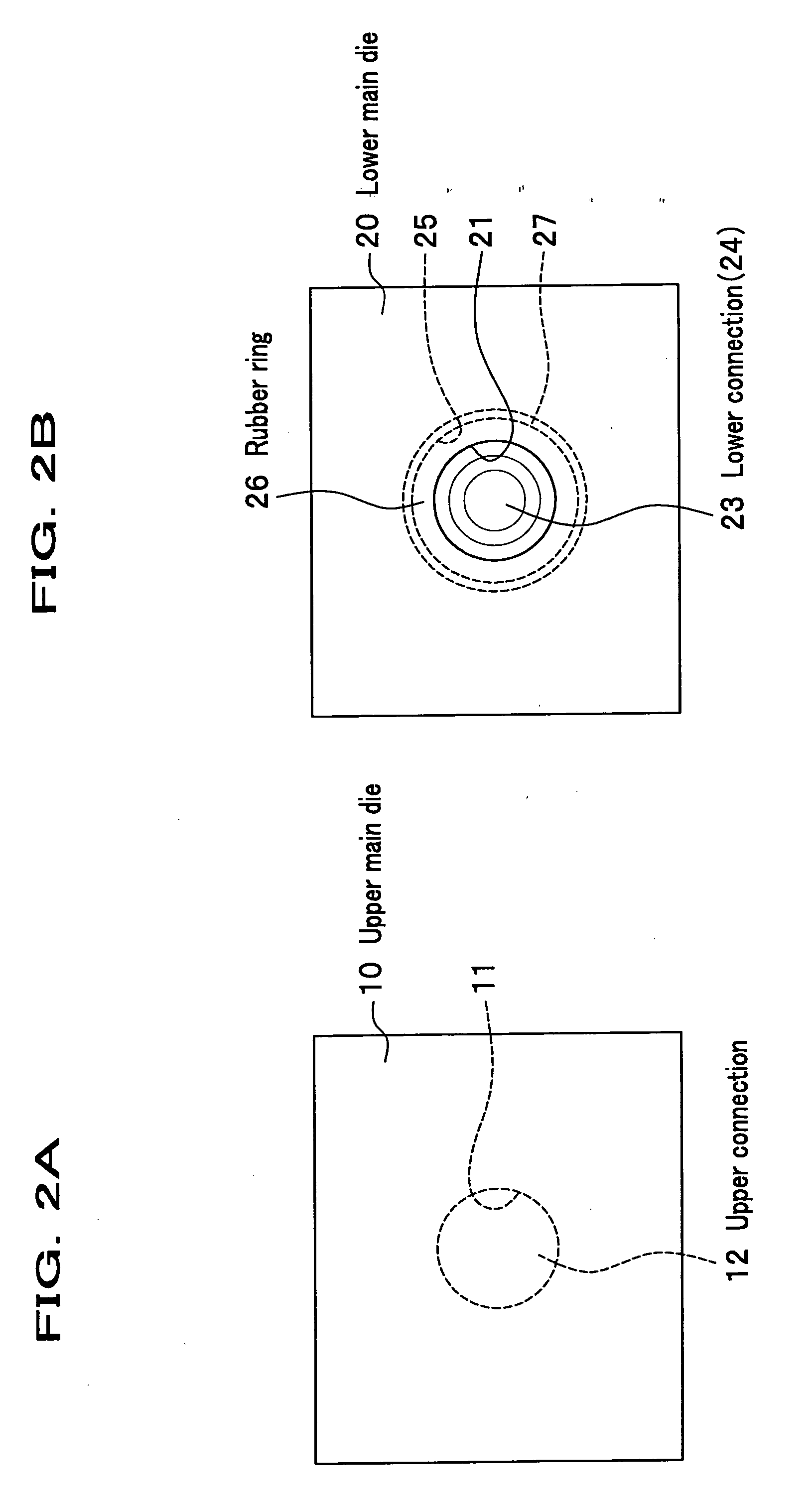
Figure 3
Abstract
Description
CROSS REFERENCE TO RELATED APPLICATIONS
[0001] This application claims the foreign priority benefit under Title 35, United States Code, §119(a)-(d) of Japanese Patent Application No. 2005-011769, filed on Jan. 19, 2005, the contents of which are hereby incorporated by reference. BACKGROUND OF THE INVENTION
[0002] 1. Technical Field of the Invention
[0003] The present invention relates to a plastic molding die for molding a plastic material.
[0004] 2. Description of the Related Art
[0005] As a plastic molding die for manufacturing a plastic lens with compression molding, using a plastic material, there is a plastic molding die which is configured so that a cavity is formed between each connection mounted on each main die of the plastic molding die when the each main die, an upper main die and a lower main die, is combined to each other.
[0006] In the plastic molding die, a plastic material is put in a space between the connections mounted on each main die when the each main die is se...
Examples
Embodiment Construction
[0038] Next, an embodiment of the present invention will be explained in detail by referring to figures.
[0039]FIGS. 1A and 1B are views showing a plastic molding die according to an embodiment of the present invention. FIG. 1A is a side cross sectional view showing each main die being separated to each other, of a plastic molding die according to the embodiment. FIG. 1B is a side cross sectional view showing each main die being engaged with each other, of the plastic molding die according to the embodiment. FIGS. 2A and 2B are views showing the plastic molding die according to the embodiment. FIG. 2A is a plane view showing an upper main die of the plastic molding die according to the embodiment. FIG. 2B is a plane view showing a lower main die of the plastic molding die according to the embodiment.
[0040] In the embodiment, an example for manufacturing a plastic lens with compression molding of a plastic material will be used for explaining the present invention.
(Configuration o...