
Tree anchor apparatus and method
Patent Information
- Authority / Receiving Office
- US · United States
- Current Assignee / Owner
- Publication Date
- 2006-08-24
- Estimated Expiration
- Not applicable · inactive patent
Smart Images
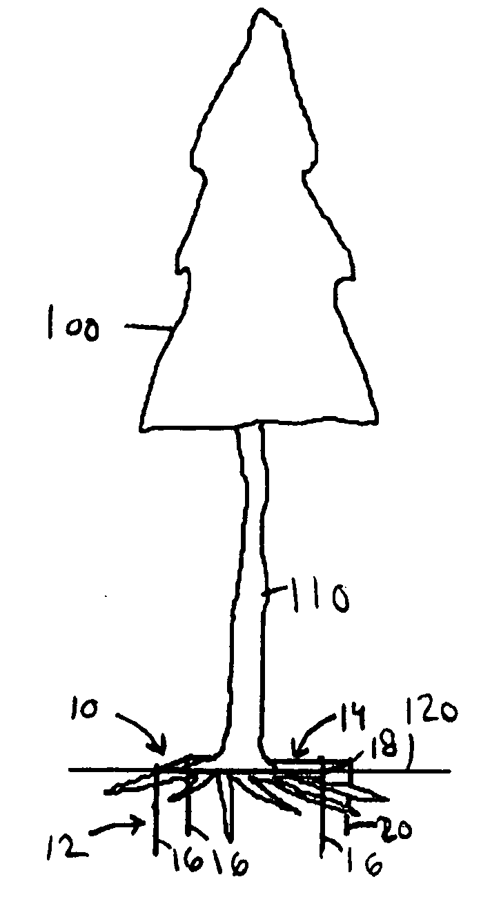
Figure 1 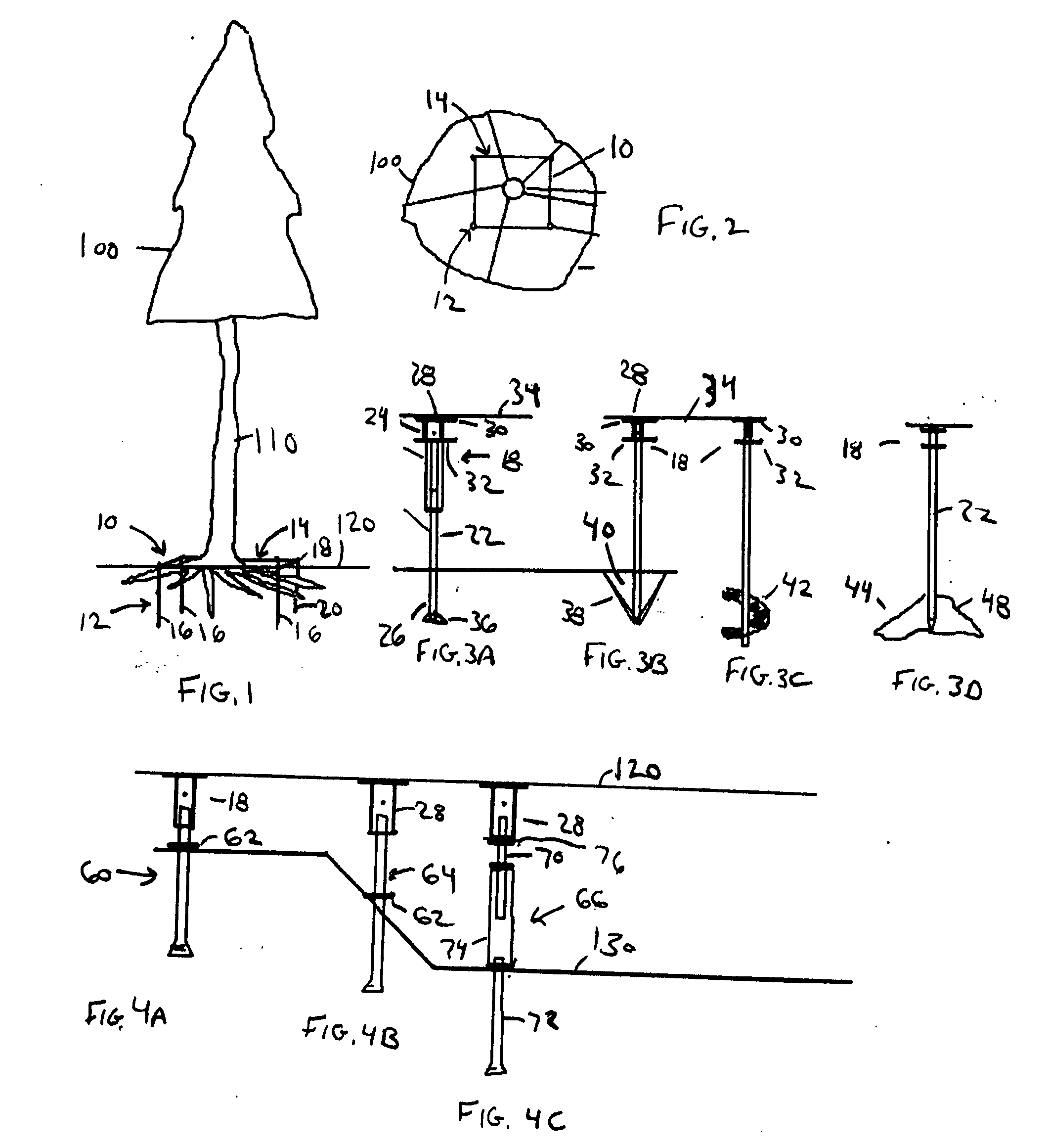
Figure 2 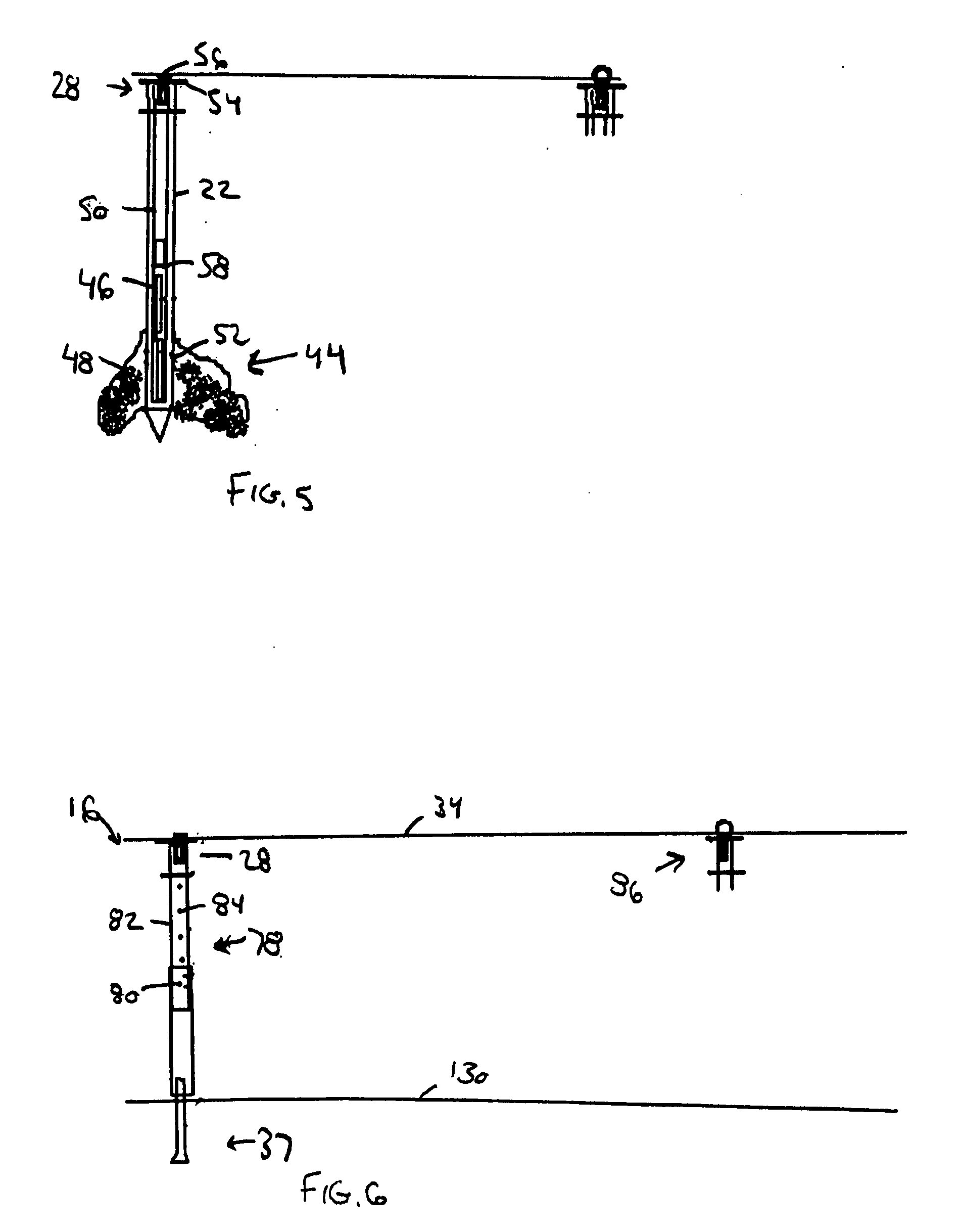
Figure 3
Abstract
Description
BACKGROUND OF THE INVENTION
[0001] 1. Field of the Invention
[0002] The present invention relates to stabilizing trees and shrubs. More particularly, the present invention relates to an apparatus and method for anchoring the root systems of trees and shrubs to the ground to assist them in remaining upright. Still more particularly, the present invention relates to a system of retention structures above the root system at or just below ground level to retain the root systems.
[0003] 2. Description of the Prior Art
[0004] It is common for trees to encounter stability problems due to a variety of conditions. For the purposes of the description of the present invention, the word tree includes trees, woody shrubs, and plants. Even the healthiest of trees can tilt or fall over completely due to conditions such as excess moisture in the ground, high winds, the unexpected application of force by an object such as a collision by a car or another tree falling. In such situations, it is often ...
Examples
fourth embodiment
[0032]FIGS. 3D and 5 show the ground anchor assembly 16 with a fourth bottom end 44 and including one or more cartridges 46 or some other means for retaining therein a liquid phase material 48 with the ability to harden, such as resin or concrete. Alternatively, the liquefied material 48 may be displaced through the end of the body 22, which in that instance would be a hollowed body, using pump or injection means applied to the top of the body 22 without an internal cartridge. After first inserting the ground anchor assembly 16 into a hole, an injection means 50 is activated to inject the liquid phase material 48 into the surrounding soil through one or more openings 52 in the bottom end 44, which injected liquid phase material 48 hardens to form a more secure anchoring platform 54. In one example, a plunger 50 is placed in the hollow portion of the bottom end 44 of the ground anchor assembly 16 as the means to force the liquid phase material 44 through the openings 52. In operation...
first embodiment
[0037]FIG. 8 shows a side view of the adjustment means 88 with an adjustment assembly 90 that includes a threaded rod 92. One end of the threaded rod 92 is screwed into the hollow portion of a connecting structure 94 suitable for connecting to a ground anchor assembly 16. The second end of the threaded rod 92 is screwed into a rotatable adjusting structure 96. Rotating the rotatable adjusting structure 96 in one direction decreases the length of the retention system 14 (and thus the tension of the retention system) by drawing the threaded rod 92 further into the rotatable adjusting structure 96 opening. Rotating the rotatable adjusting structure 96 in the other direction has the opposite effect. The end of the rotatable adjusting structure 96 opposite from the end connected to the threaded rod 92 is connected to the cable 34, which, in turn, is suitable for connecting to a ground anchor assembly 16 as previously described.
[0038]FIG. 9 shows a second embodiment of the adjustment mean...