
Pole support tube
Patent Information
- Authority / Receiving Office
- US · United States
- Current Assignee / Owner
- Publication Date
- 2006-10-26
- Estimated Expiration
- Not applicable · inactive patent
Smart Images
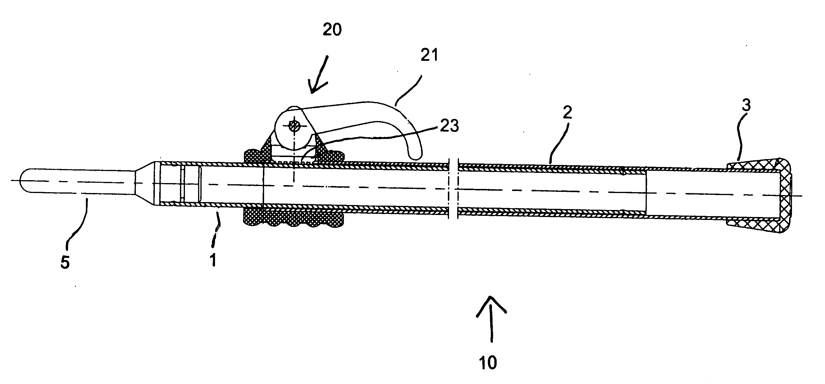
Figure 1 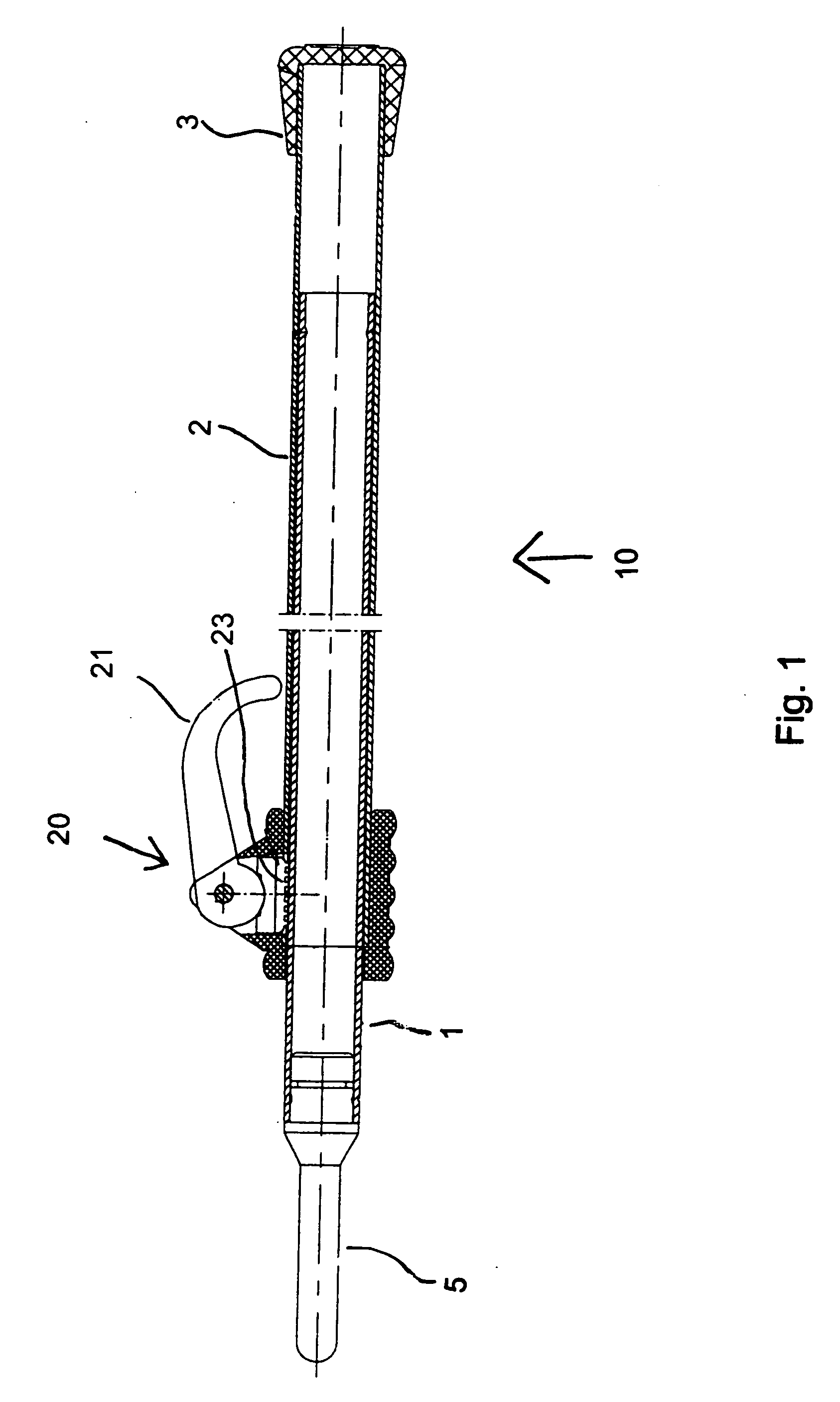
Figure 2 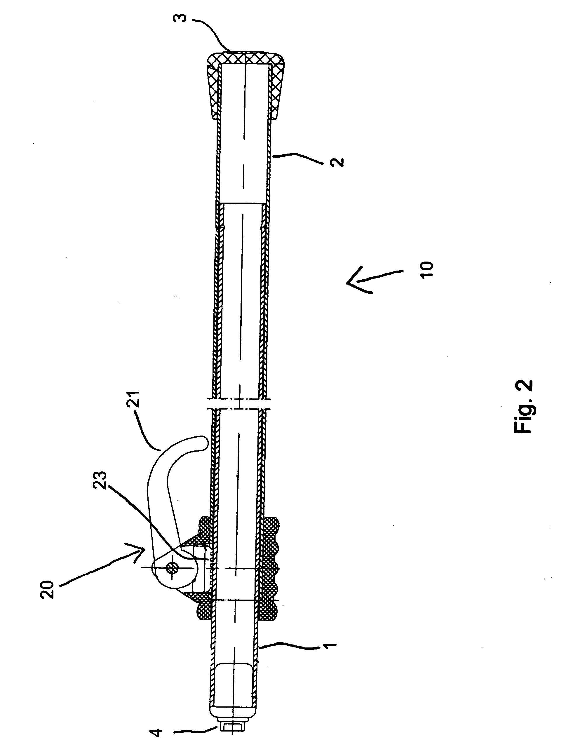
Figure 3
Abstract
Description
CROSS-REFERENCE TO RELATED APPLICATIONS
[0001] This application claims the benefit of U.S. Provisional Application Ser. No. 60 / 667,621, filed on Apr. 1, 2005, entitled Pole Support Tube; the prior application is herewith incorporated by reference in its entirety.BACKGROUND OF THE INVENTION
[0002] 1. Field of the Invention
[0003] The present invention pertains to a pole support tube which supports a canvas tarp or cover. More specifically, to a pole support tube that can support a tarp that has a load applied thereon.
[0004] 2. Description of the Related Art
[0005] Pole support tubes are generally used in the rear of a boat. One or more of the pole support tubes may be used to support a canvas. The pole support tube(s) serve to support the canvas to prevent weather (snow, ice, water etc.) from puddling or pooling on the canvas (FIG. 4).
[0006] A pole support tube includes two sections; one section is an outer section and the other section is an inner section, such that the inner sect...
Examples
Embodiment Construction
[0024] Referring now to the figures of the drawing in detail and first, particularly, FIGS. 1, 2, and 3 illustrate a pole support tube having an inner section or inner tube 1 and an outer section or outer tube 2. Included on a free end of the outer section 2 is a rubber foot 3. The inner section includes either a universal snap end 4 (FIG. 2) or a tent pole type end 5 (FIG. 2), or as shown in FIG. 3 the inner section 1 can have both the universal snap 4 and the tent pole type end 5 on opposite ends thereof.
[0025] The pole support tube 10 can be adjusted to infinite extended lengths by a cam assembly 20. The cam assembly 20 is disposed on the outer section 2 at the outer diameter of the outer section 2. The cam assembly 20 includes a rotatable lever 21 that allows for a quick and easy setting of the length of the pole support tube. The lever 21 activates a pressure pad 23 that engages the outer diameter of the inner section 1 through a hole formed in the outer section. In the activa...