
Air passage opening/closing system
a technology of air passage and opening/closing, which is applied in the direction of vehicle components, vehicle cleaning, vehicle heating/cooling devices, etc., can solve the problems of rack, and affecting the operation of the pinion. , to achieve the effect of reducing the noise of the occurrence of malfunctions and reducing the noise of the pinion
Patent Information
- Authority / Receiving Office
- US · United States
- Patent Type
- Applications(United States)
- Current Assignee / Owner
- Publication Date
- 2007-05-17
- Estimated Expiration
- Not applicable · inactive patent
Smart Images
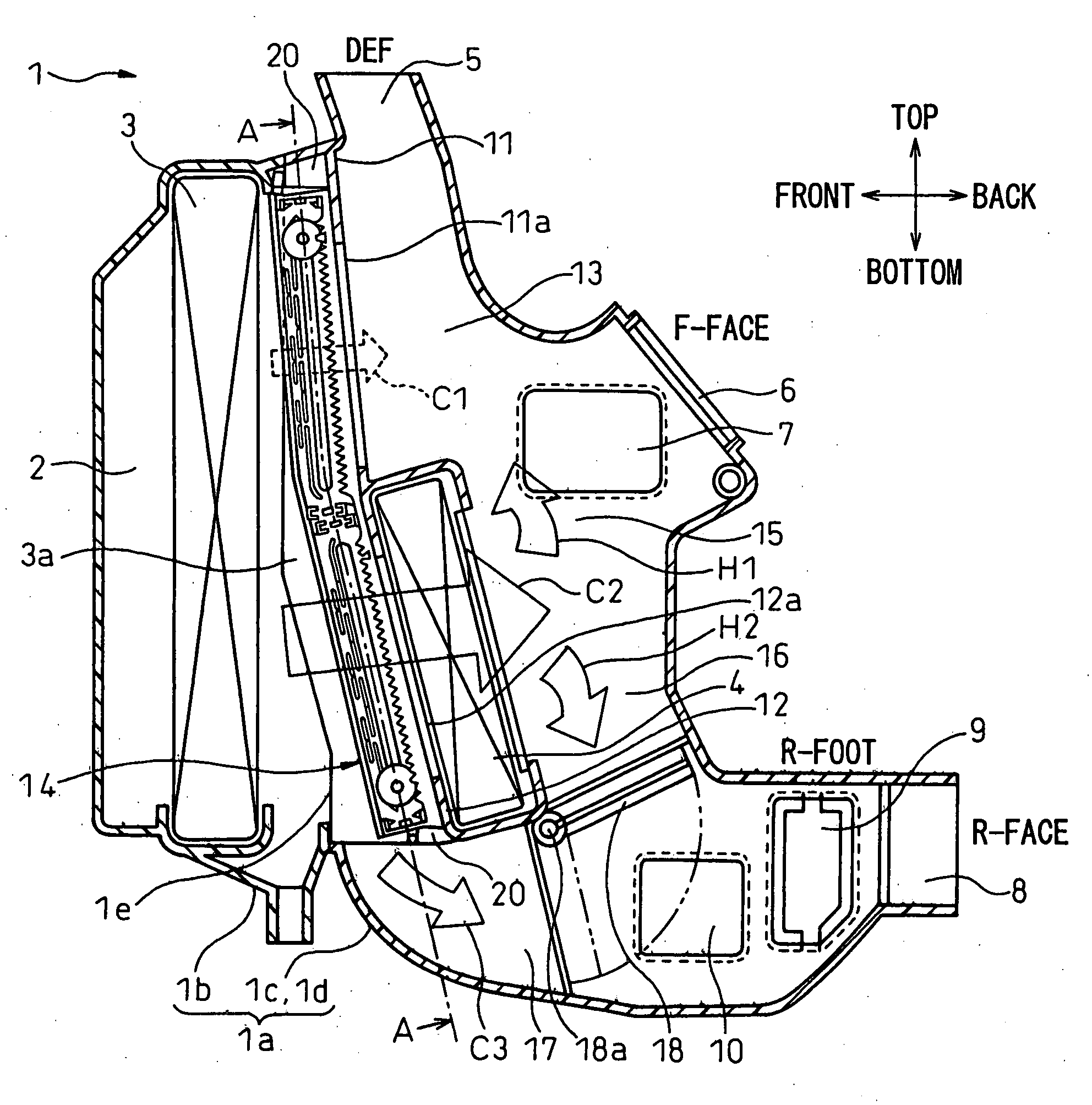
Figure 1 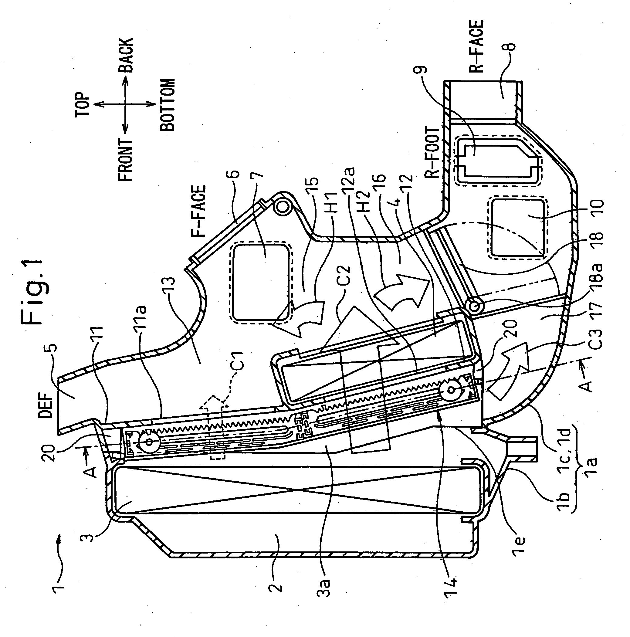
Figure 2 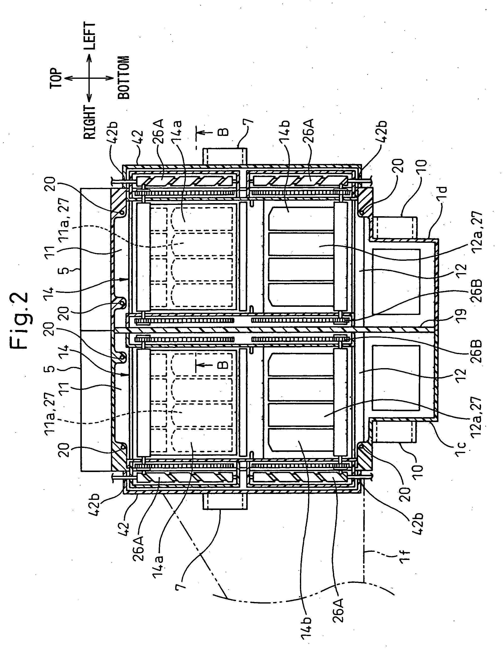
Figure 3
Abstract
Description
BACKGROUND OF THE INVENTION
[0001] 1. Field of the Invention
[0002] The present invention relates to an air passage opening / closing system opening and closing an air passage by a film-shaped member (film door) and suitable for use in a vehicle air-conditioning system.
[0003] 2. Description of the Related Art
[0004] In the past, an air passage opening / closing system using this type of film-shaped member to open and close an air passage was proposed in Japanese Patent Publication (A) No. 2005-199988.
[0005] In the prior art of this Japanese Patent Publication (A) No. 2005-199988, one end of the film-shaped member is fixed to the outside of the opening of the air passage, the other end of the film-shaped member is connected to a film-shaped member windup shaft, and this film-shaped member windup shaft rotates and moves in a direction away from and approaching one end of the film-shaped member (side where film-shaped member is fixed), whereby the film-shaped member is wound up or fed ou...
Examples
first embodiment
[0062] Below, a first embodiment of the present invention will be explained based on FIG. 1 to FIG. 6. FIG. 1 shows the overall configuration in the case of applying the present invention to a vehicle air-conditioning system, while FIG. 2 is a cross-sectional view of the part A-A in FIG. 1.
[0063] The air-conditioning unit 1 of the vehicle air-conditioning system in this embodiment has a plastic air-conditioner case 1a. This air-conditioner case 1a is positioned at the inside from the instrument panel in the passenger compartment of the vehicle at the approximate center location in the vehicle width (left-right) direction and is positioned as shown by the arrows of FIG. 1 and FIG. 2 with respect to the front-back, top-bottom, and left-right directions of the vehicle.
[0064] The air-conditioner case 1a, for convenience in removal from the mold in the case of molding and due to reasons such as assembly of the air-conditioner in the case, is specifically formed divided into a plurality...
second embodiment
[0161] In the first embodiment, part of the cold air passes through the relief holes 39 of the first partition walls 37 and flows to the windup shaft drive mechanisms 26A and 26B, but in the second embodiment, as shown in FIGS. 7A and 7B, film-shaped blocking members 43 are arranged at the relief holes 39 to block cold air from passing through the relief holes 39, so extraneous materials can be better prevented from depositing at the windup shaft drive mechanisms 26A and 26B.
[0162]FIG. 7A is a schematic cross-sectional view of principal parts of the cold air passage opening / closing unit 14a of the film door 14 in the present embodiment, while FIG. 7B shows the state with the cold air side opening 11a fully opened in FIG. 7A.
[0163] Note that the hot air passage opening / closing unit 14b is substantially the same in configuration as the cold air passage opening / closing unit 14a, so the illustration and explanation are omitted.
[0164] As the film-shaped blocking members 43 in the pres...
third embodiment
[0175] In the above second embodiment, film-shaped blocking members 43 are positioned at the relief holes 39 to block cold air from passing through the relief holes 39, but in the third embodiment, as shown in FIGS. 8A and 8B, multilayer slide doors 44 are positioned at the relief holes 39 to block the cold air from passing through the relief holes 39.
[0176]FIG. 8A is a schematic cross-sectional view of principal parts of the cold air passage opening / closing unit 14a of the film door 14 in the present embodiment and shows the state with the cold air side opening 11a fully closed, while FIG. 8B shows the state with the cold air side opening 11a fully opened in FIG. 8A.
[0177] Note that hot air passage opening / closing unit 14b is substantially the same in configuration as the cold air passage opening / closing unit 14a, so the illustration and explanation are omitted.
[0178] The multilayer slide doors 44 in the present embodiment use the basic structure of the multilayer slide doors in...