
Solid-state imaging device
Patent Information
- Authority / Receiving Office
- US · United States
- Current Assignee / Owner
- Publication Date
- 2008-04-17
- Estimated Expiration
- Not applicable · inactive patent
Smart Images
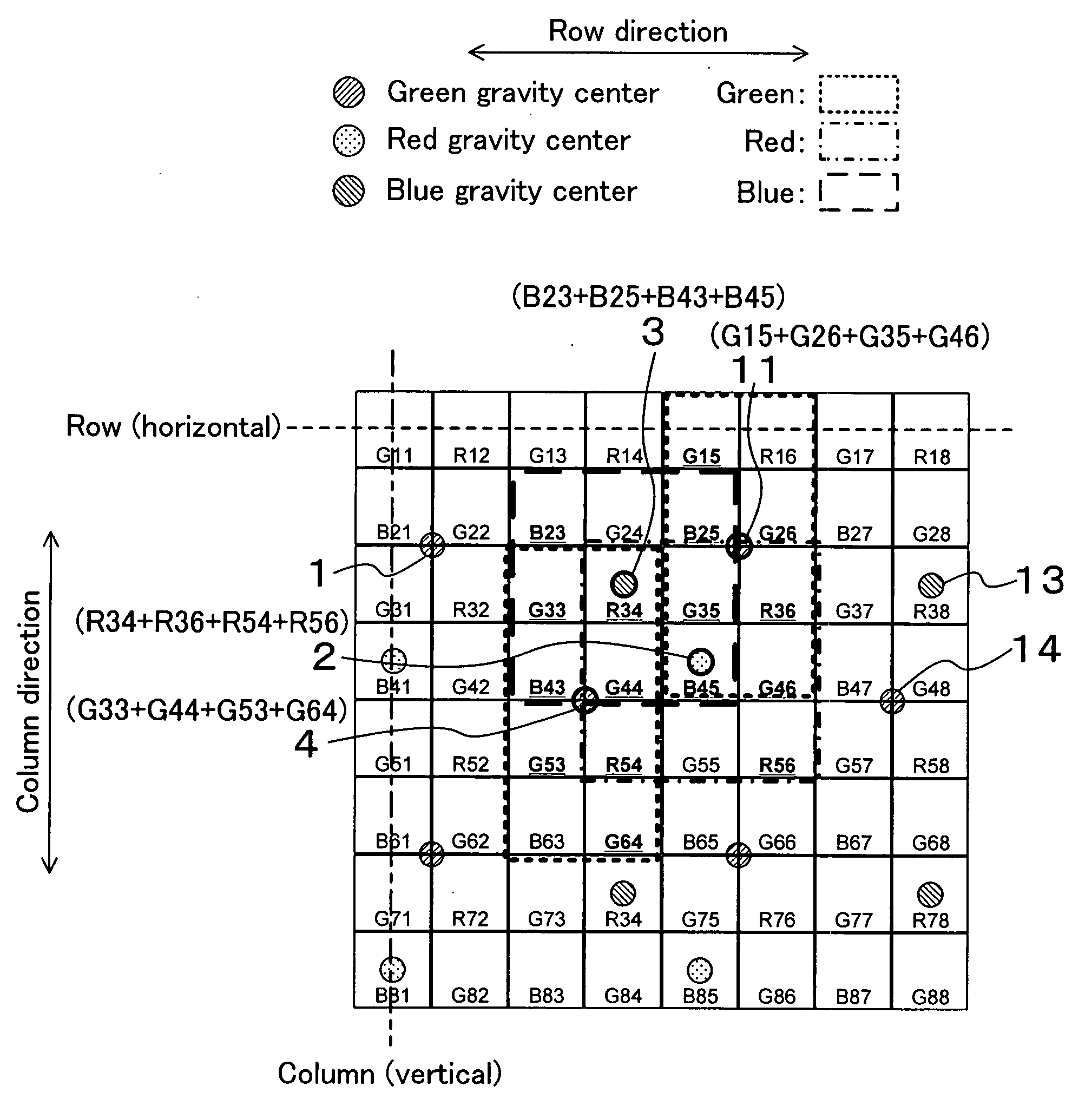
Figure 1 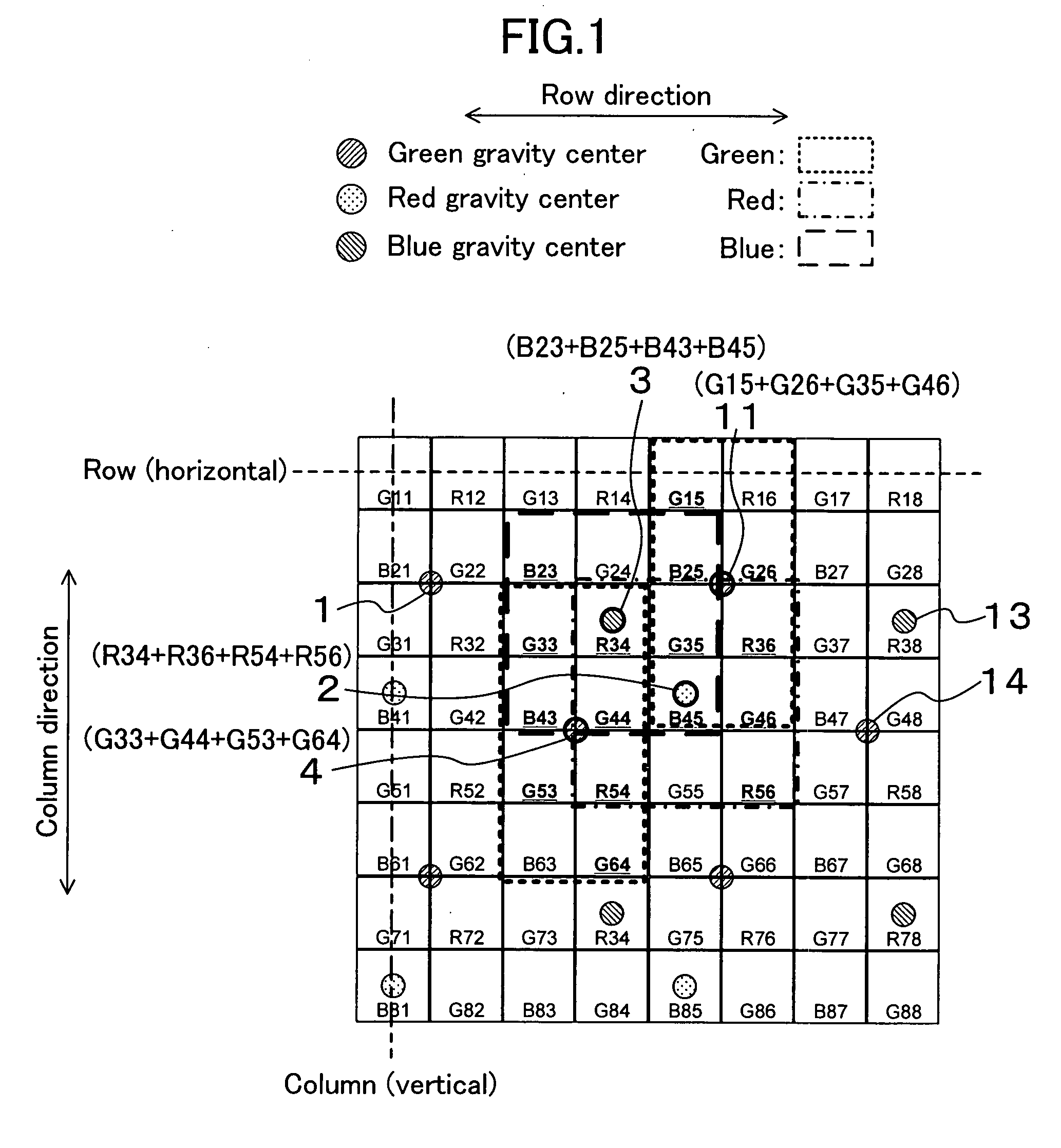
Figure 2 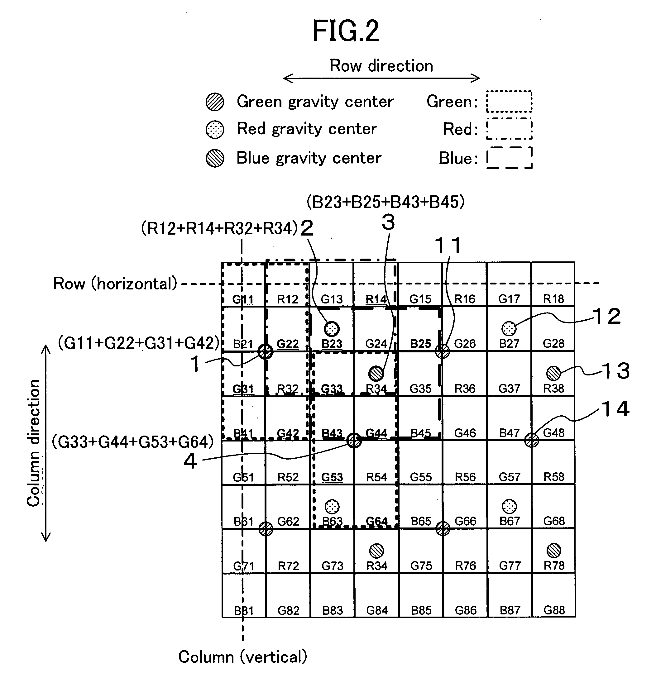
Figure 3
Abstract
Description
BACKGROUND OF THE INVENTION
[0001] 1. Technical Field
[0002] The present invention relates to a solid-state imaging device with a pixel addition mode.
[0003] 2. Related Art
[0004] Further improvement in image quality and functions is demanded in imaging devices such as digital still cameras, and solid-state imaging devices mounted on the imaging devices employ a technique to implement a high speed by a pixel addition or pixel mixture method. Explanation will be made for a solid-state imaging device according to a conventional technique disclosed in Japanese Patent Application Publication No. 2004-312140, the entire contents of which being herein incorporated in reference, with reference to drawings.
[0005] FIG. 25 is a configuration diagram of the solid-state imaging device disclosed in Japanese Patent Application Publication No. 2004-312140.
[0006] Reference numeral 1011 is a photoelectric conversion element and a color filter attached to a front surface thereof. It is assumed here that a colo...
Examples
first embodiment
[0052]Explained below will be a solid-state imaging device and a driving method thereof according to a first embodiment of the present invention with reference to drawings.
[0053]FIG. 1 is an image diagram showing a pixel addition pattern of the solid-state imaging device and the driving method thereof according to the first embodiment of the present invention.
[0054]As shown in FIG. 1, a color filter array is a Bayer array, for example. A filter pixel held by an R filter on both horizontal sides is made to be Gr, and a filter pixel held by a B filter on both horizontal sides is made to be Gb for convenience of explaining an operation, but Gr and Gb are the same color in practice.
[0055]As shown in FIG. 1, green (hereinafter referred to as G) G15, G26, G35, and G46 are formed into a first G group, G33, G44, G53, and G64 are formed into a second G group, red (hereinafter referred to as R) R34, R54, R36, and R56 are formed into an R group, blue (hereinafter referred to as B) B23, B25, B4...
modified example 1 of first embodiment
[0101]A solid-state imaging device and a driving method thereof according to a modified example 1 of the first embodiment of the present invention will be explained below by referring to a diagram. Any one of the first to fourth configurations of the solid-state imaging device according to the first embodiment as shown in FIG. 5, FIG. 7, FIG. 10, and FIG. 15 is used for a device configuration of the solid-state imaging device according to this modified example 1.
[0102]FIG. 2 is an image diagram showing a pixel addition pattern of the solid-state imaging device and the driving method thereof according to the modified example 1 of the first embodiment of the present invention.
[0103]As shown in FIG. 2, a color filter array is a Bayer array, for example, in which a filter pixel held by an R filter on both horizontal sides is made to be Gr, and a filter pixel held by a B filter on both horizontal sides is made to be Gb for convenience of explaining an operation, but Gr and Gb are the sam...
modified example 2 of first embodiment
[0105]A solid-state imaging device and a driving method thereof according to a modified example 2 of the first embodiment of the present invention will be explained below by referring to a diagram. Any one of the first to fourth configurations of the solid-state imaging device according to the first embodiment of the present invention as shown in FIG. 5, FIG. 7, FIG. 10, and FIG. 15 is used for a device configuration of the solid-state imaging device according to this modified example 2 of the first embodiment of the present invention.
[0106]FIG. 3 is an image diagram showing a pixel addition pattern of the solid-state imaging device and the driving method thereof according to the modified example 2 of the first embodiment of the present invention.
[0107]As shown in FIG. 3, a color filter array is a Bayer array, for example, in which a filter pixel held by an R filter on both horizontal sides is made to be Gr, and a filter pixel held by a B filter on both horizontal sides is made to b...