
Display device with image pickup device
A technology for a display device and a camera device, which is applied to projection devices, printing devices, identification devices, etc., can solve the problems of low yield photodiodes, small number of photodiodes, and increased cost.
Patent Information
- Authority / Receiving Office
- CN · China
- Patent Type
- Patents(China)
- Current Assignee / Owner
- Publication Date
- 2009-08-26
- Estimated Expiration
- Not applicable · inactive patent
Smart Images
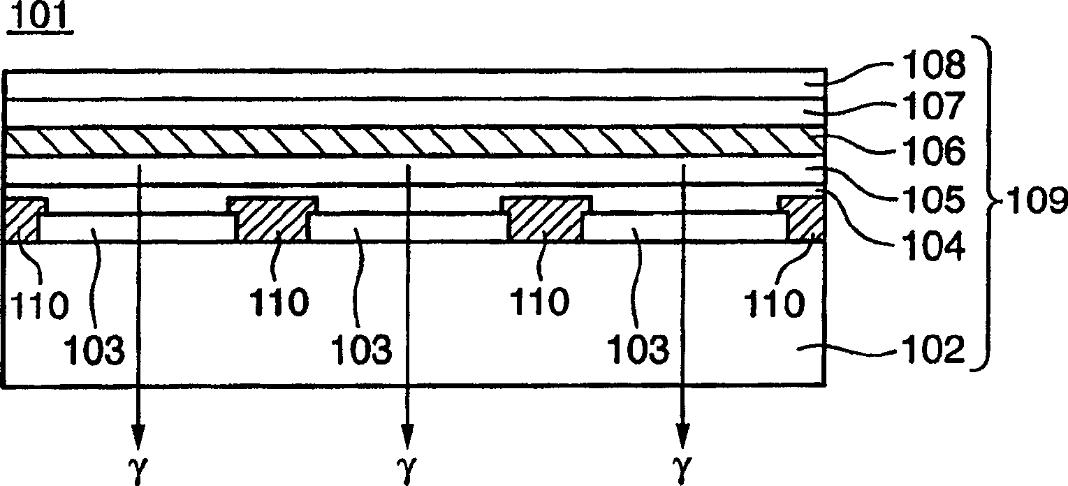
Figure 1 
Figure 2 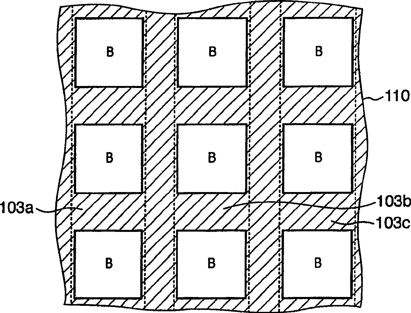
Figure 3
Abstract
Description
technical field
[0001] The present invention relates to a display device with an imaging device including an imaging device integrated with a relatively thin display device such as organic EL, liquid crystal, or plasma type. More specifically, it relates to a display device with an imaging device which is suitable for real-time two-way communication such as a videophone or the like. Background technique
[0002] In recent years, with the astonishing development of communication networks, real-time two-way communication such as videophones has become possible. A videophone is composed of an imaging unit that converts a subject image into an electrical image signal, and a display unit that converts the electrical image signal into an optical signal and displays it. The user of the videophone conducts a conversation while looking at the other party's face displayed on the screen of the display unit, and at the same time uses the camera unit to photograph the user's face and co...
Examples
no. 1 Embodiment approach
[0059] The first embodiment is an example in which an organic EL (electroluminescence) element is used as a display unit. The organic EL element is a self-luminous element, and when used in a display device, it has: (1) high luminous efficiency; (2) low driving voltage; (3) various colors (green and green) can be displayed by selecting a light-emitting material. , red, blue, yellow, etc.); (4) does not require a backlight source; (5) is surface-emitting, no viewing angle dependence; and (6) thin, light weight and other good features. Therefore, in recent years, a display device using an organic EL element has attracted attention as a display device replacing a CRT or an LCD. Next, before describing the present embodiment, first, an organic EL display device will be described.
[0060] There are a simple matrix type and an active matrix type in a dot matrix organic EL display device that performs display using dots (dots) arranged in a matrix.
[0061] The simple matrix metho...
no. 2 Embodiment approach
[0140] The second embodiment is a modified example of the first embodiment, and shows an example in which the density of display pixels is increased, the display resolution is improved, and a large diaphragm aperture can be secured even if the aperture ratio of the display pixels is increased.
[0141] Figure 15 , 16 is an example of the case of having a camera unit in a full-color display unit, Figure 15 It is a plan view of the display unit 113 in the second embodiment seen from the anode 103 side, Figure 16 It is a plan view of the display unit 113 in the second embodiment seen from the cathode 108 side, and corresponds to the first embodiment respectively. Figure 5 , Figure 6 . also, Figure 15 Other components other than the anode 103 and the cathode 108 are omitted, Figure 16 Components other than the black matrix 110 are omitted. In addition, this embodiment mode is applicable to all of the five modes described about the full-color mode in the first embodim...
no. 3 Embodiment approach
[0151] The third embodiment shows an example in which a higher-resolution captured image is obtained without increasing the thickness of the entire device by using an imaging device that performs pixel shifting using a compound-eye optical system.
[0152] An imaging device disclosed in Japanese Unexamined Patent Application Publication No. 2002-209226 is known as an imaging device that performs pixel offset imaging using a compound-eye optical system. In this imaging device, four subject images are formed by four lens units, and images are captured in four imaging areas. At this time, a so-called pixel shift imaging is performed, and positions shifted by 1 / 2 pixel in each of the four imaging areas are sampled. Furthermore, by sampling subject images of different wavelength bands in the four imaging areas, and combining the images, an image equivalent to the known Bayer arrangement can be obtained. In this embodiment, this imaging device is used as the imaging unit 112 .
[...