
Faucet structure having pressure balance valves
a technology of pressure balance valve and valve body, which is applied in the field of faucets, can solve the problems of increasing the complexity and difficulty of the manufacturing process, affecting the maintenance of the valve body, increasing the product cost, etc., and achieves the effects of reducing cost, simplifying the manufacturing process, and convenient maintenance or replacemen
Patent Information
- Authority / Receiving Office
- US · United States
- Patent Type
- Applications(United States)
- Current Assignee / Owner
- Publication Date
- 2009-08-20
- Estimated Expiration
- Not applicable · inactive patent
Smart Images
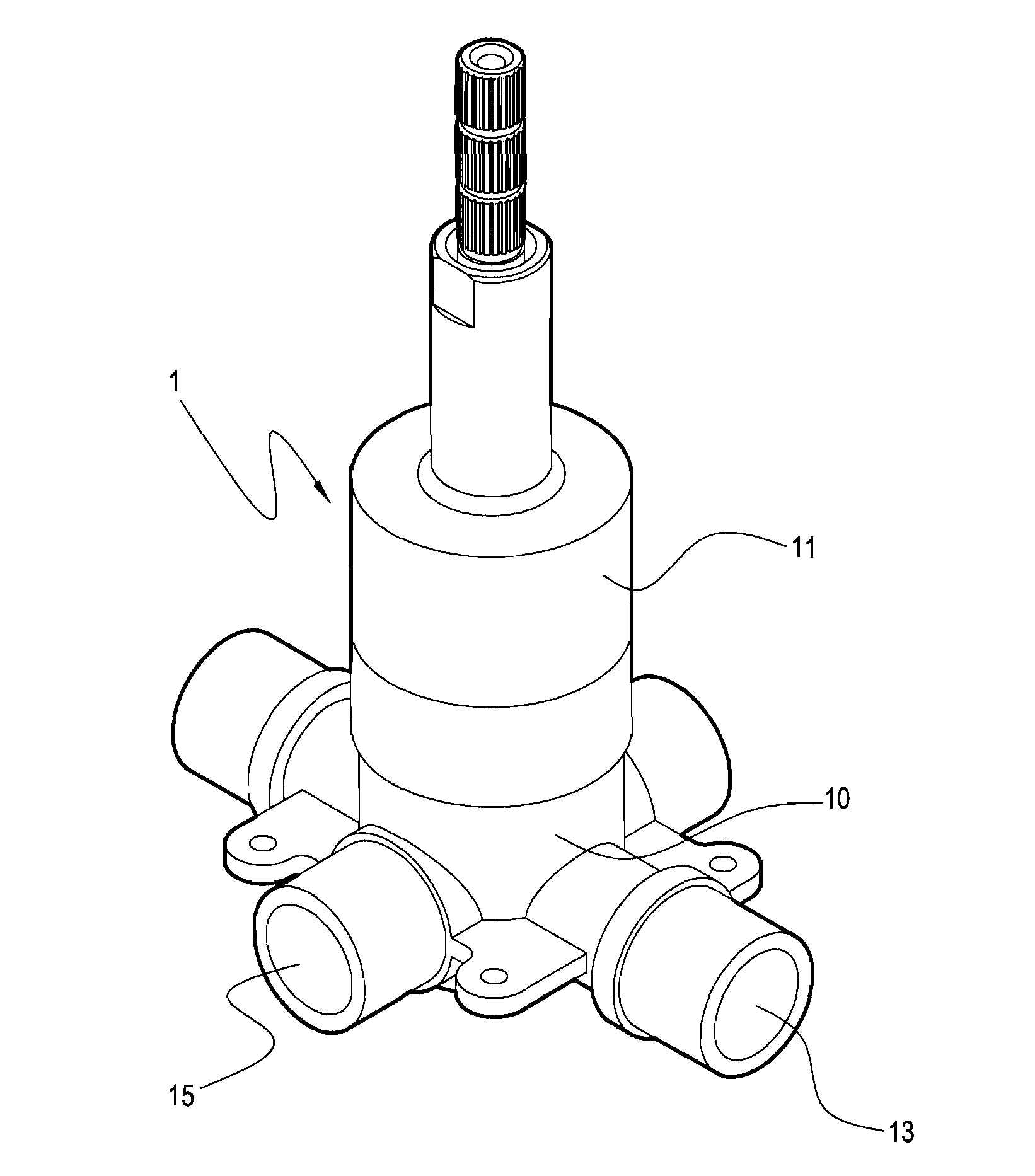
Figure 1 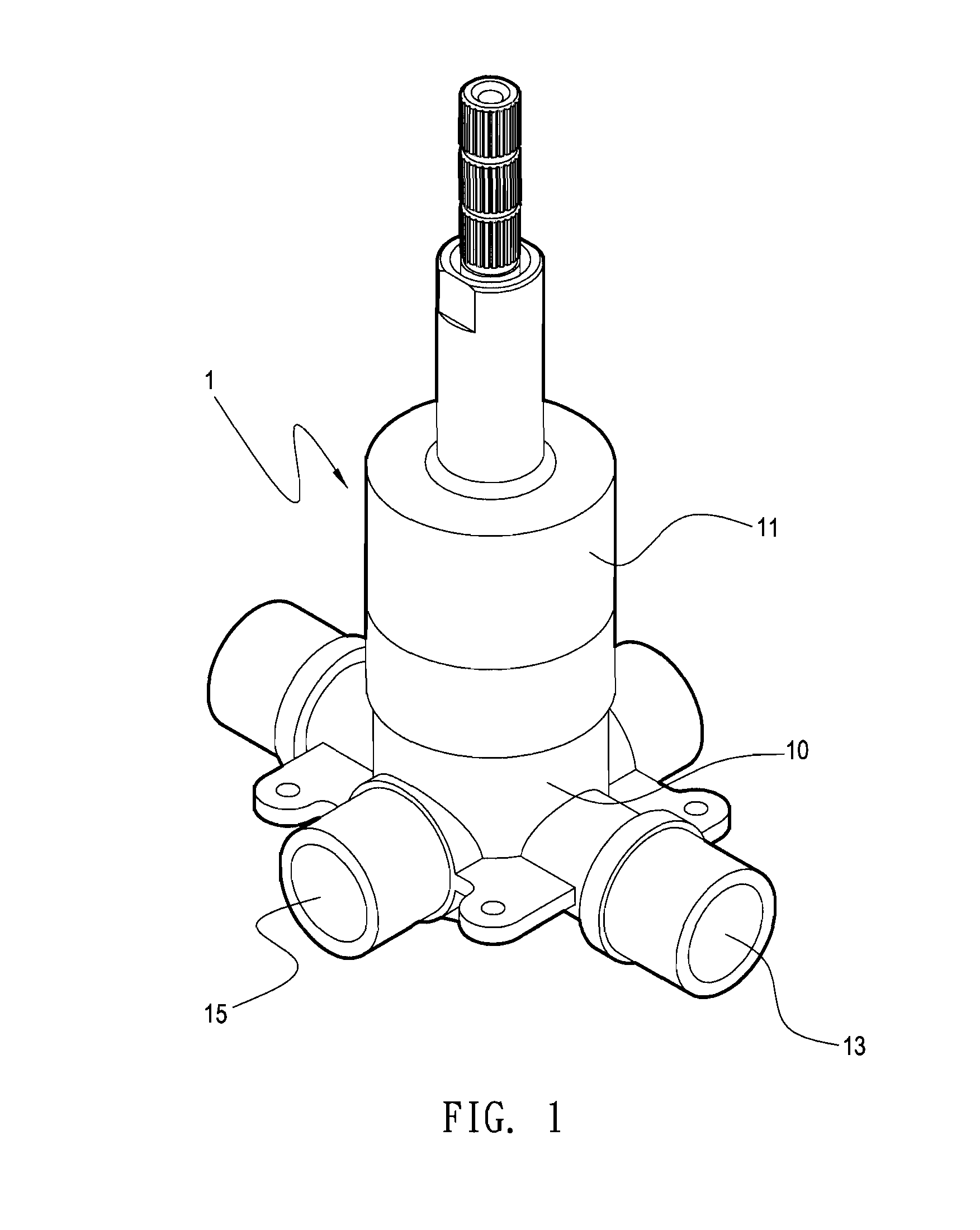
Figure 2 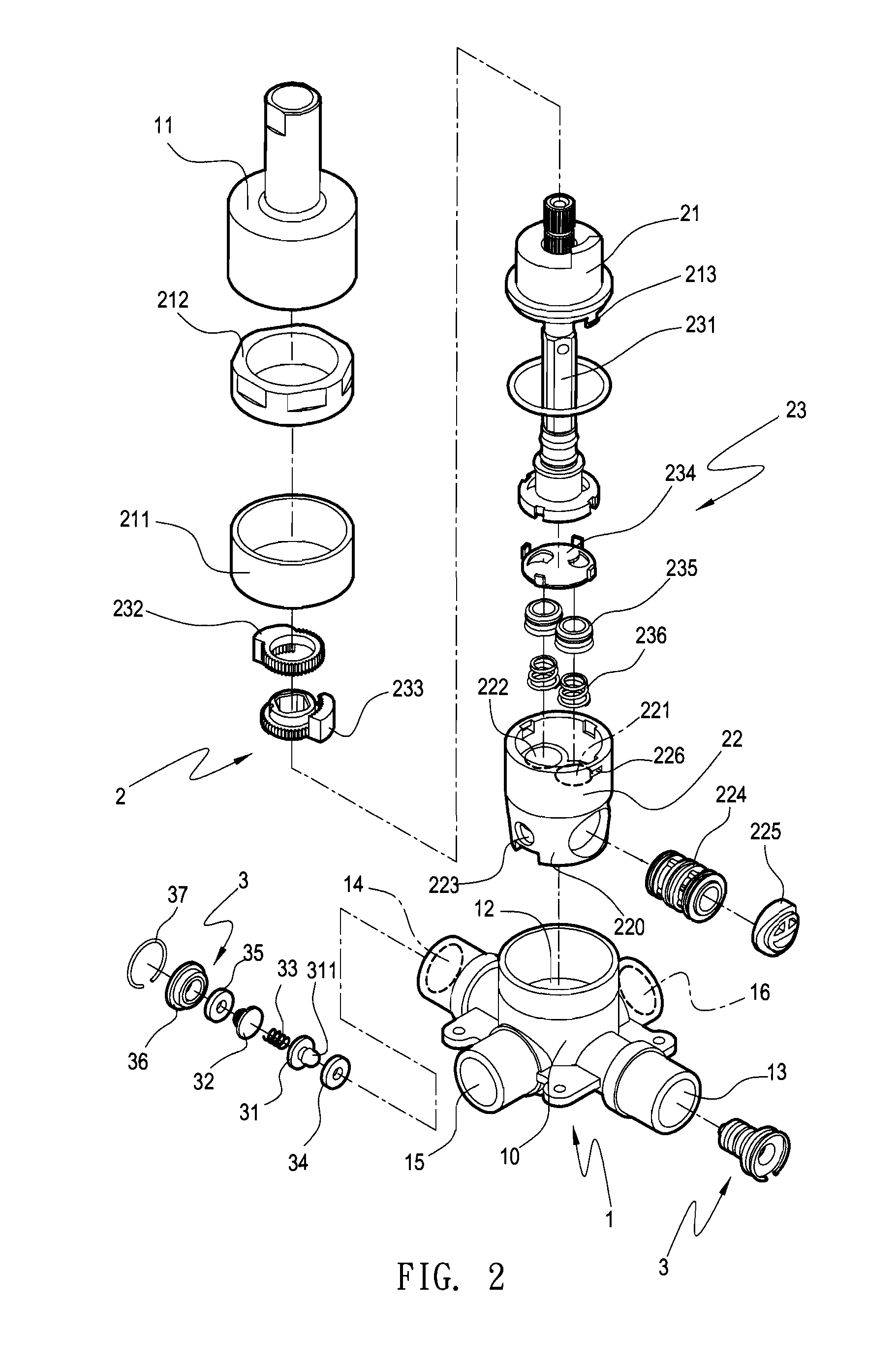
Figure 3
Abstract
Description
BACKGROUND OF THE INVENTION
[0001] 1. Field of the Invention
[0002] The present invention generally relates to a faucet, in particular, to a faucet structure having pressure balance valve sets therein and capable of automatically closing a water entry when detaching a control valve set.
[0003] 2. Description of Related Art
[0004] Referring to FIG. 6, it shows a conventional faucet, which mainly includes a valve seat 8 and a body 9.
[0005] The valve seat 8 has a valve chamber 81, and has two water entries 82, 83 and one water exit 84 disposed within the valve chamber 81. The two water entries 82, 83 extend to penetrate the valve seat 8, so as to respectively form inlet pipes 82a, 83a. The water exit 84 extends to penetrate the valve seat 8, so as to form two outlet pipes 84a, 84b that are communicated with each other.
[0006] A control valve set (not shown) is disposed within the body 9, and is manipulated through a handle 91. The control valve set has water inlets 92, 93 and a water outlet 94 re...
Examples
Embodiment Construction
[0025]Reference will now be made in detail to the present preferred embodiments of the invention, examples of which are illustrated in the accompanying drawings. Wherever possible, the same reference numbers are used in the drawings and the description to refer to the same or like parts.
[0026]Referring to FIGS. 1 to 5, they show a structure of a preferred embodiment of the present invention.
[0027]Referring to FIGS. 1 and 2, FIG. 1 is an outside view of the present invention, and FIG. 2 is an exploded perspective view of the present invention.
[0028]The faucet of the present invention includes a valve seat 1, a control valve set 2, and two pressure balance valve sets 3.
[0029]The valve seat 1 includes a seat body 10 and a cover 11, and once the seat body 10 and the cover 11 are combined together, the control valve set 2 may be disposed therein. The seat body 10 has a valve chamber 12 therein, and has two water entries 13, 14 and two water exits 15, 16 communicating with the exterior fr...