
Electric power tool
Patent Information
- Authority / Receiving Office
- US · United States
- Current Assignee / Owner
- Publication Date
- 2009-10-15
- Estimated Expiration
- Not applicable · inactive patent
Smart Images
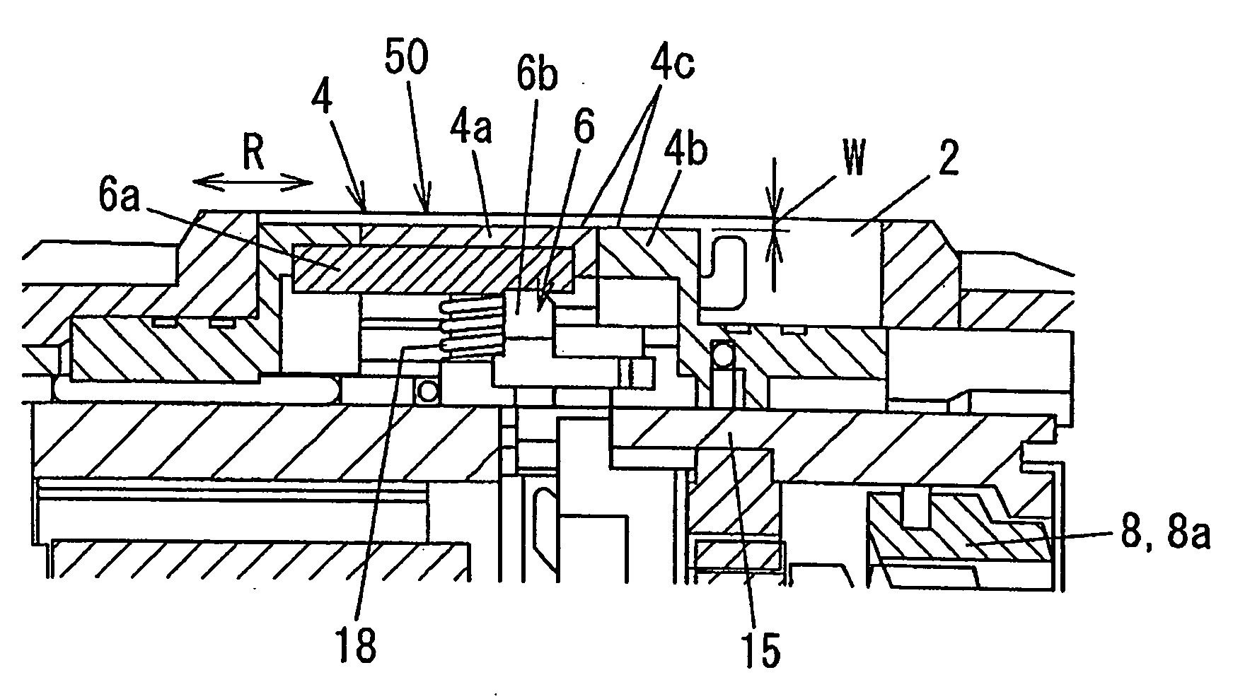
Figure 1 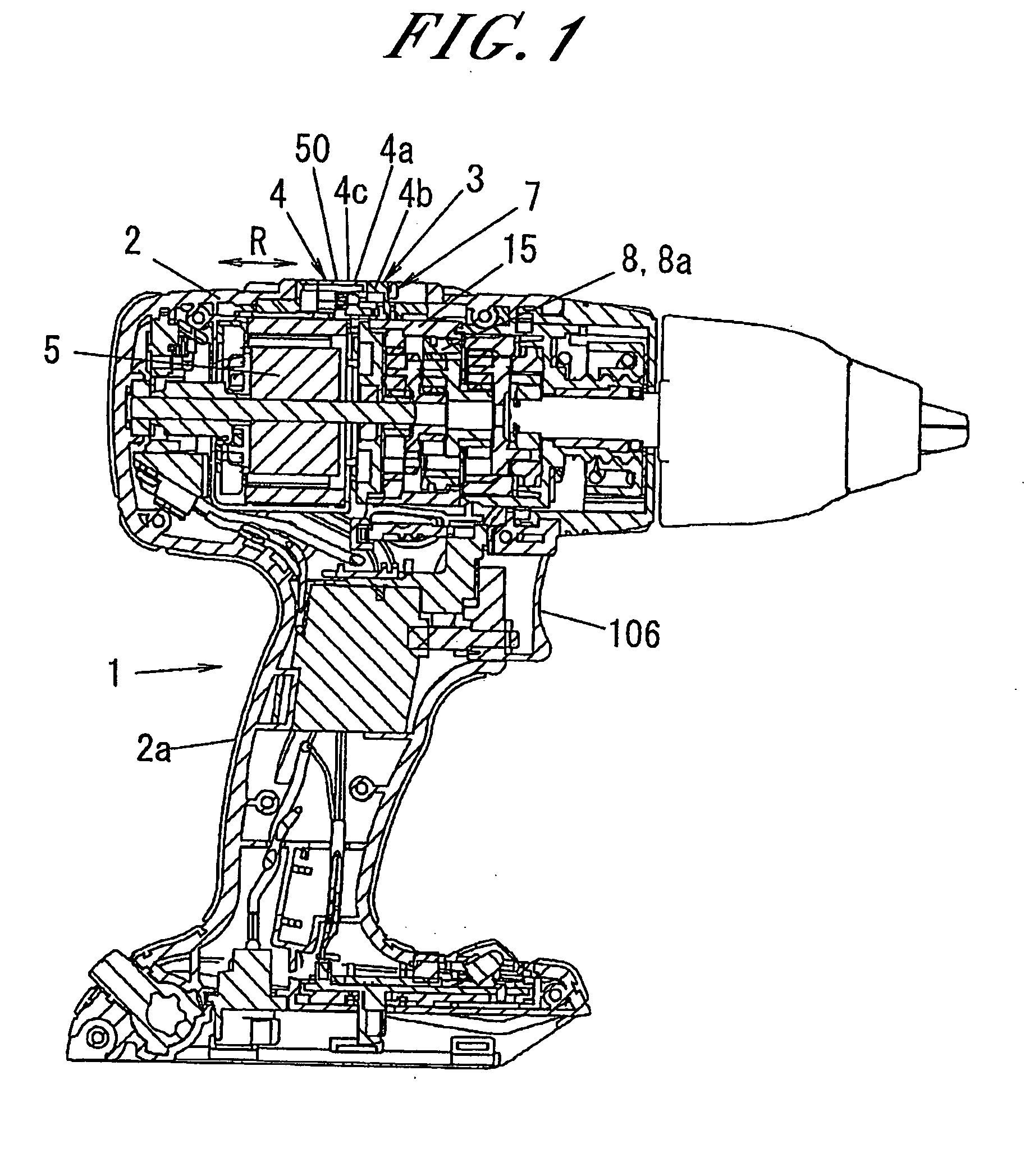
Figure 2 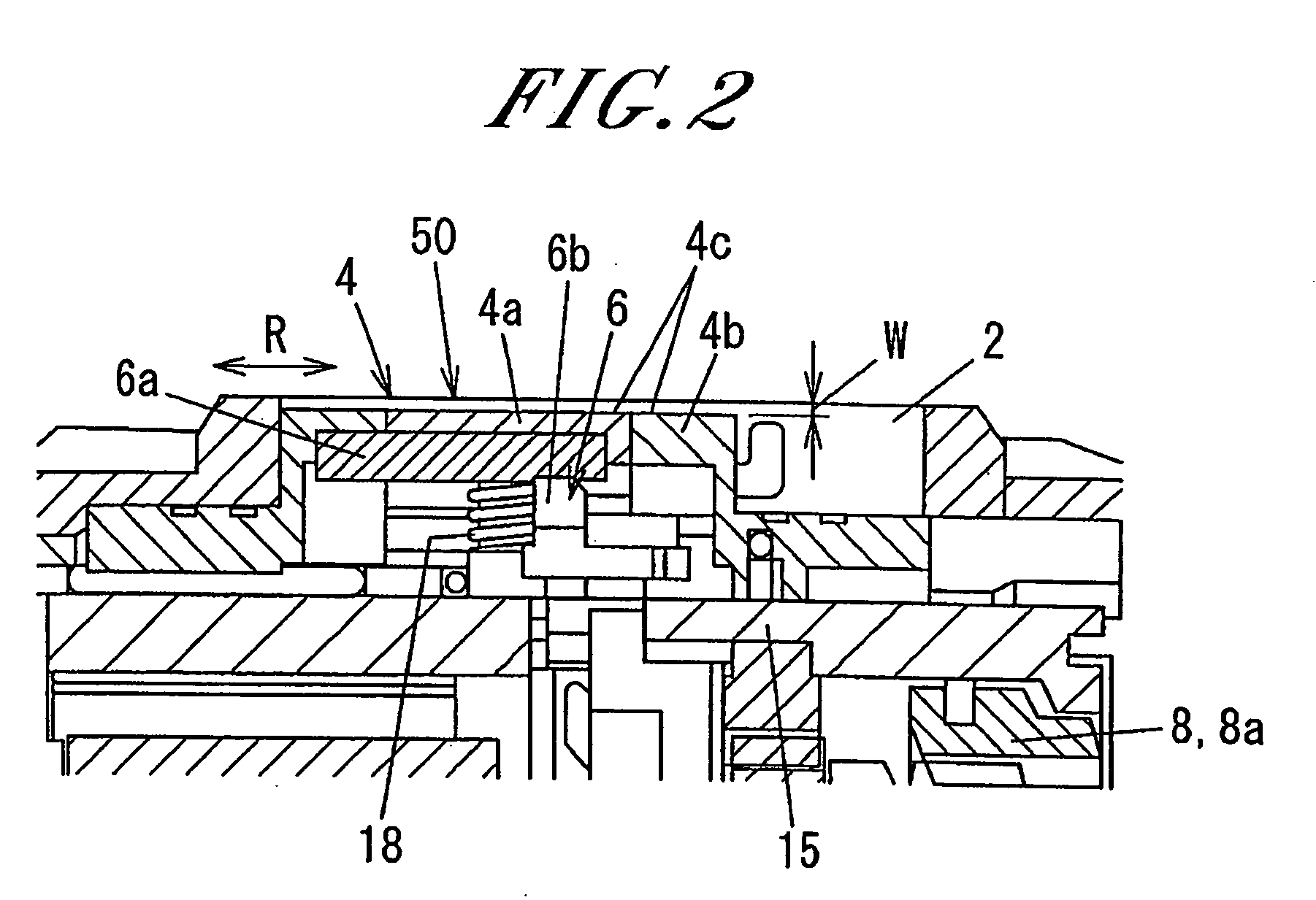
Figure 3
Abstract
Description
FIELD OF THE INVENTION
[0001] The present invention relates to an electric power tool, such as a drill driver, a disc saw or the like, which has a speed changing function performed by a speed reduction mechanism.BACKGROUND OF THE INVENTION
[0002] In general, there are known electric power tools that have a speed changing function with a view to enhance work efficiency (see, e.g., Japanese Patent Laid-open Publication No. 63-101545).
[0003] One example of the electric power tools is shown in FIG. 15. This electric power tool includes a motor 101 as a driving power source, a speed reducer unit 102 for delivering the rotational power of the motor 101 at a reduced speed, a drive unit (not shown) for delivering the rotational power of the speed reducer unit 102 to a tip end tool, a resin-made housing 104 provided with a handle portion 104a and arranged to contain the motor 101 and the speed reducer unit 102 therein, an operation lever 105 and a shift unit 105a, both of which serve as a speed c...
Examples
Embodiment Construction
[0042]Hereinafter, an embodiment of the present invention will be described with reference to the accompanying drawings which form a part hereof.
[0043]Referring to FIG. 1, the electric power tool 1 of the present embodiment essentially includes a motor 5 as a driving power source, a speed reducer unit 8 arranged to deliver the rotational power of the motor 5 and provided with two or more gears 8a, a driving unit arranged to deliver the rotational power of the speed reducer unit 8 to a tip end tool, a bearing unit for rotatably supporting the driving unit, a housing 2 arranged to accommodate the motor 5, the speed reducer unit 8, the driving unit and the bearing unit therein and provided with a handle portion 2a, and a speed changing mechanism 3 for changing the gear reduction ratio of the speed reducer unit 8, the speed changing mechanism 3 being arranged in a position where it can be operated outside the housing 2. In FIG. 1, reference numeral 106 designates a power switch for swit...