
Rear-focus zoom lens device and video camera
Patent Information
- Authority / Receiving Office
- US · United States
- Current Assignee / Owner
- Publication Date
- 2005-06-28
- Estimated Expiration
- Not applicable · inactive patent
Smart Images
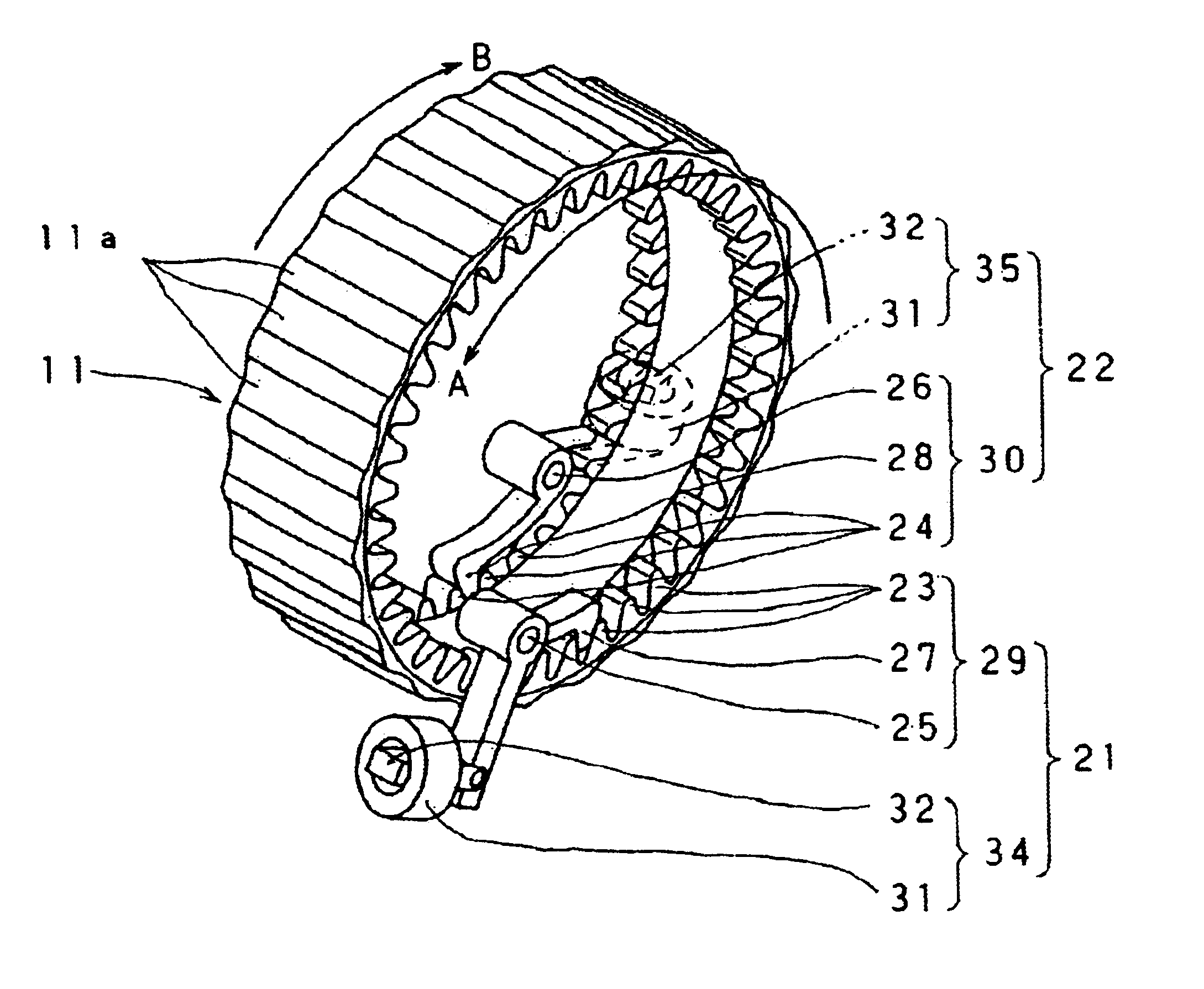
Figure 1 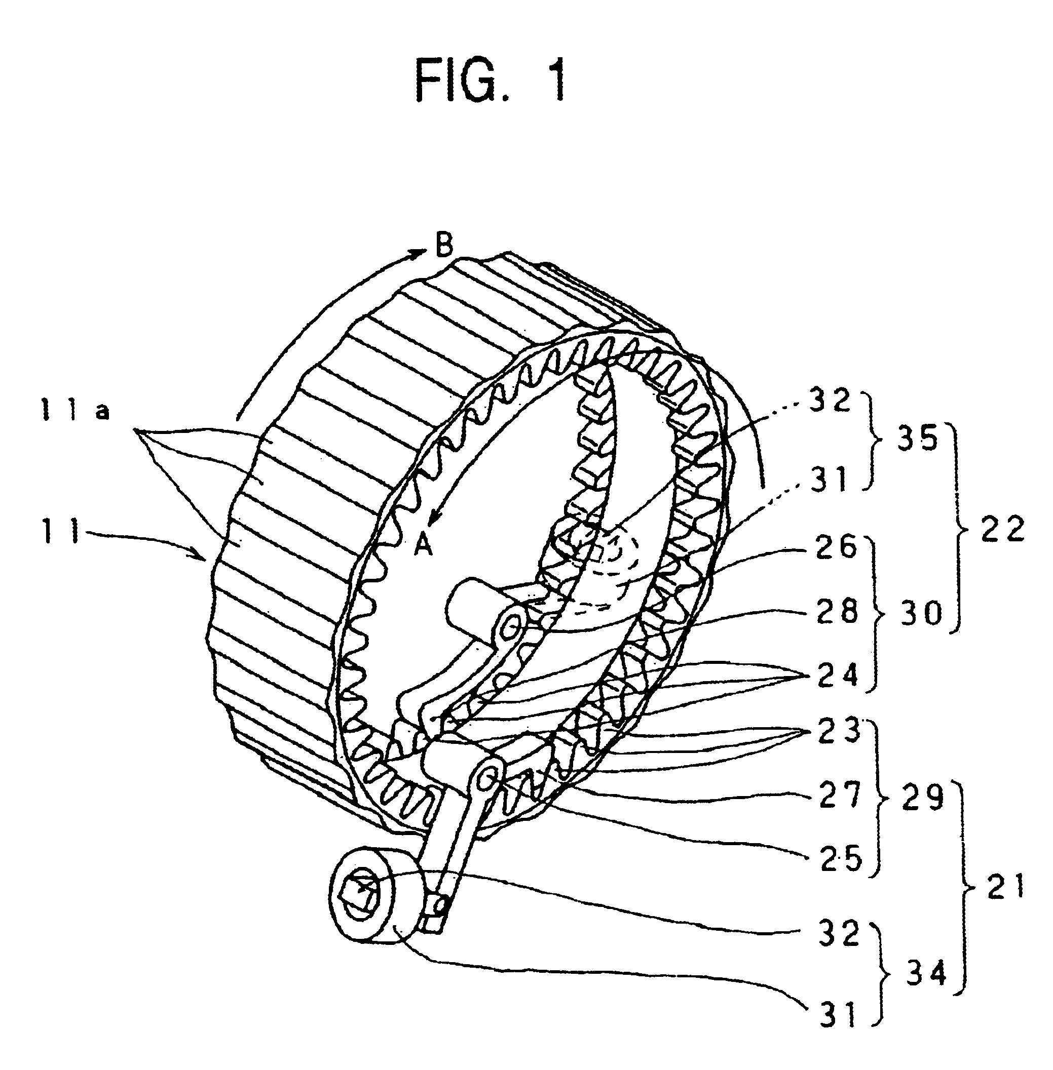
Figure 2 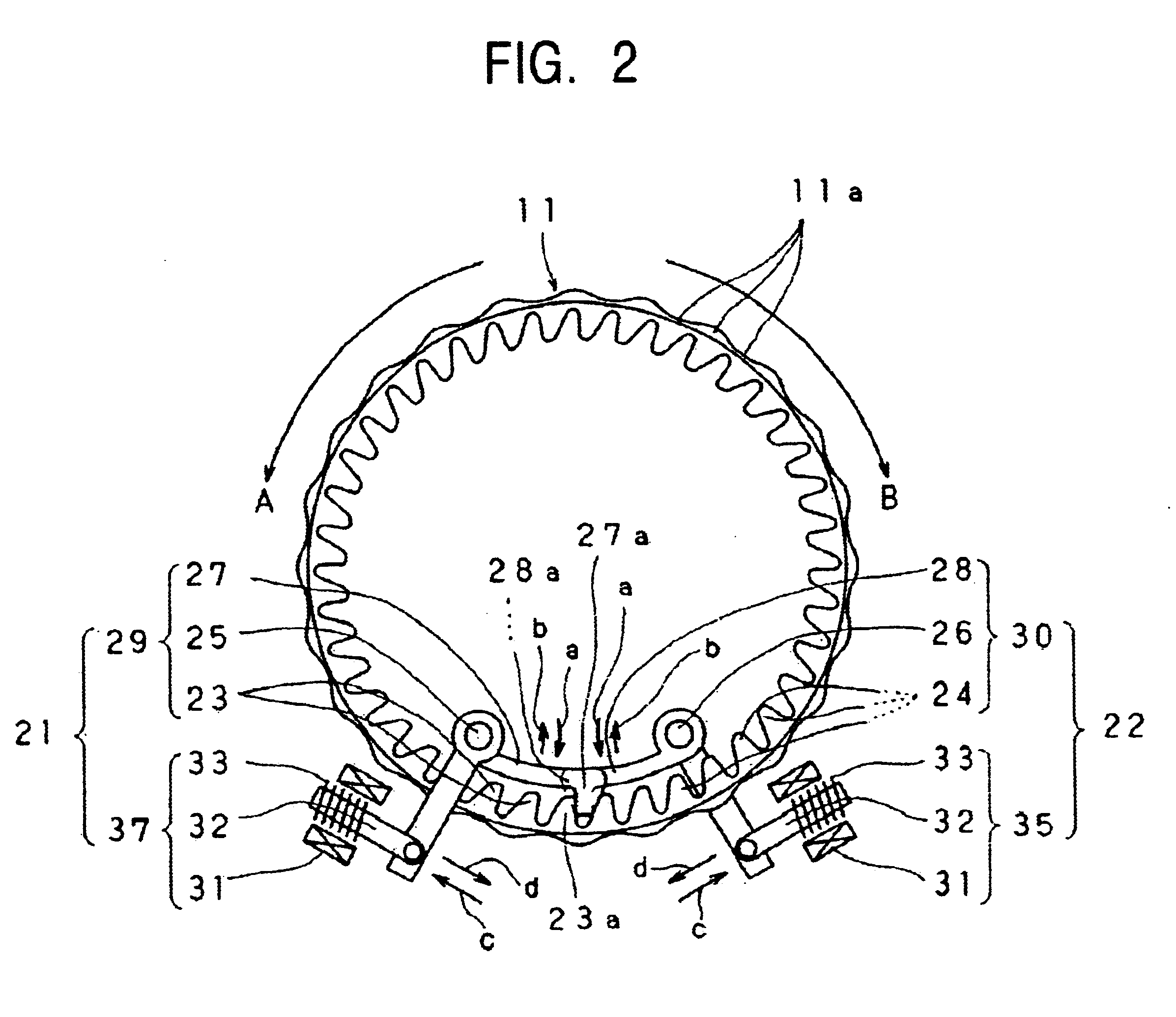
Figure 3
Abstract
Description
BACKGROUND OF THE INVENTION
[0001] 1. Field of the Invention
[0002] The present invention relates to the technical field of a rear-focus zoom lens device for carrying out zooming by a zooming lens, which is a combination lens, disposed at an end of a lens barrel, and for carrying out focusing by a focusing lens, which is a combination lens, disposed rearward of the zooming lens. The present invention also relates to the technical field of a video camera including the rear-focus zoom lens device.
[0003] 2. Description of the Related Art
[0004] As is widely known, two types of zoom lens devices are used in, for example, video cameras. They are a front-focus zoom lens device and a rear-focus zoom lens device. In the front-focus zoom lens device, focusing is carried by a focusing lens, which is a combination lens, disposed at an end of a lens barrel, and zooming is carried out by a zooming lens, which is a combination lens, disposed rearward of the focusing lens. In the rear-focus zoom lens dev...
Examples
second embodiment
(2) Second Embodiment
[0088]Next, a zoom lens device 1 of a second embodiment of the present invention will be given with reference to FIGS. 9 to 11. In this case, the aforementioned wide-angle direction rotation restricting means 21 and the telephoto direction rotation restricting means 22 are attached to the rotary ring 110 which rotates in response to the movement of the aforementioned zoom ring 11.
[0089]The wide-angle direction rotation restricting means 21 comprises a ratchet mechanism 29 and an actuator 34. The telephoto direction rotation restricting means 22 comprises a ratchet mechanism 30 and an actuator 35. The ratchet mechanism 29 comprises a ratchet pawl 23 and a ratchet pawl arm 27. The ratchet mechanism 30 comprises a ratchet pawl 24 and a ratchet pawl arm 28. The ratchet pawls 23 and 24 are disposed in an annular form along the entire outer periphery at respective ends of the rotary ring 110 in an axial direction. The ratchet pawl arms 27 and 28 are disposed at the ou...
third embodiment
(3) Third Embodiment
[0094]Next, a description of a zoom lens device 1 of a third embodiment of the present invention will be given with reference to FIGS. 12 to 17. In this case, a wide-angle direction stepless rotation restricting means 210 and a telephoto direction stepless rotation restricting means 220 for restricting the rotation at stepless positions on the circumference of a zoom ring 11 are formed as the wide-angle direction rotation restricting means 21 and the telephoto direction rotation restricting means 22 for the zoom ring 11.
[0095]The wide-angle direction stepless rotation restricting means 210 and the telephoto direction stepless rotation restricting means 220 comprise, for example, respective roller compression surfaces 61 and 62, respective unidirectional rotation compression rollers 63 and 64, respective compression arms 67 and 68, and respective actuators 72 and 73. The roller compression surfaces 61 and 62 are smooth surfaces formed at the inner peripheral surfa...