
Disc-shaped filter elements and methods to provide disc-shaped filter elements
a technology of filter elements and discs, applied in the direction of filtration separation, manufacturing tools, separation processes, etc., can solve the problems of disc forming distortion, improper cleaning of discs, and disturbance of the proper use of disc forming filters, so as to reduce the risk of filter membrane rupture during cleaning and be less sensitive to production parameter fluctuations
Patent Information
- Authority / Receiving Office
- US · United States
- Patent Type
- Applications(United States)
- Current Assignee / Owner
- Publication Date
- 2010-01-21
- Estimated Expiration
- Not applicable · inactive patent
Smart Images
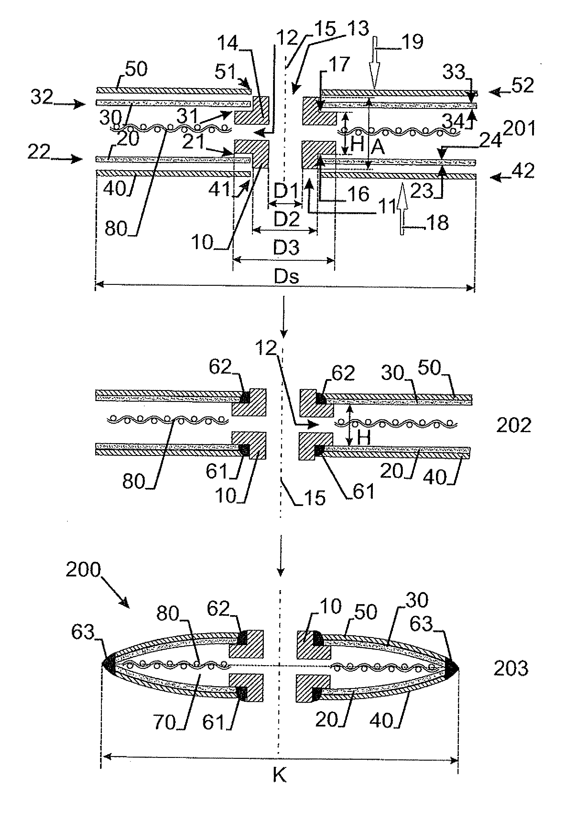
Figure 1 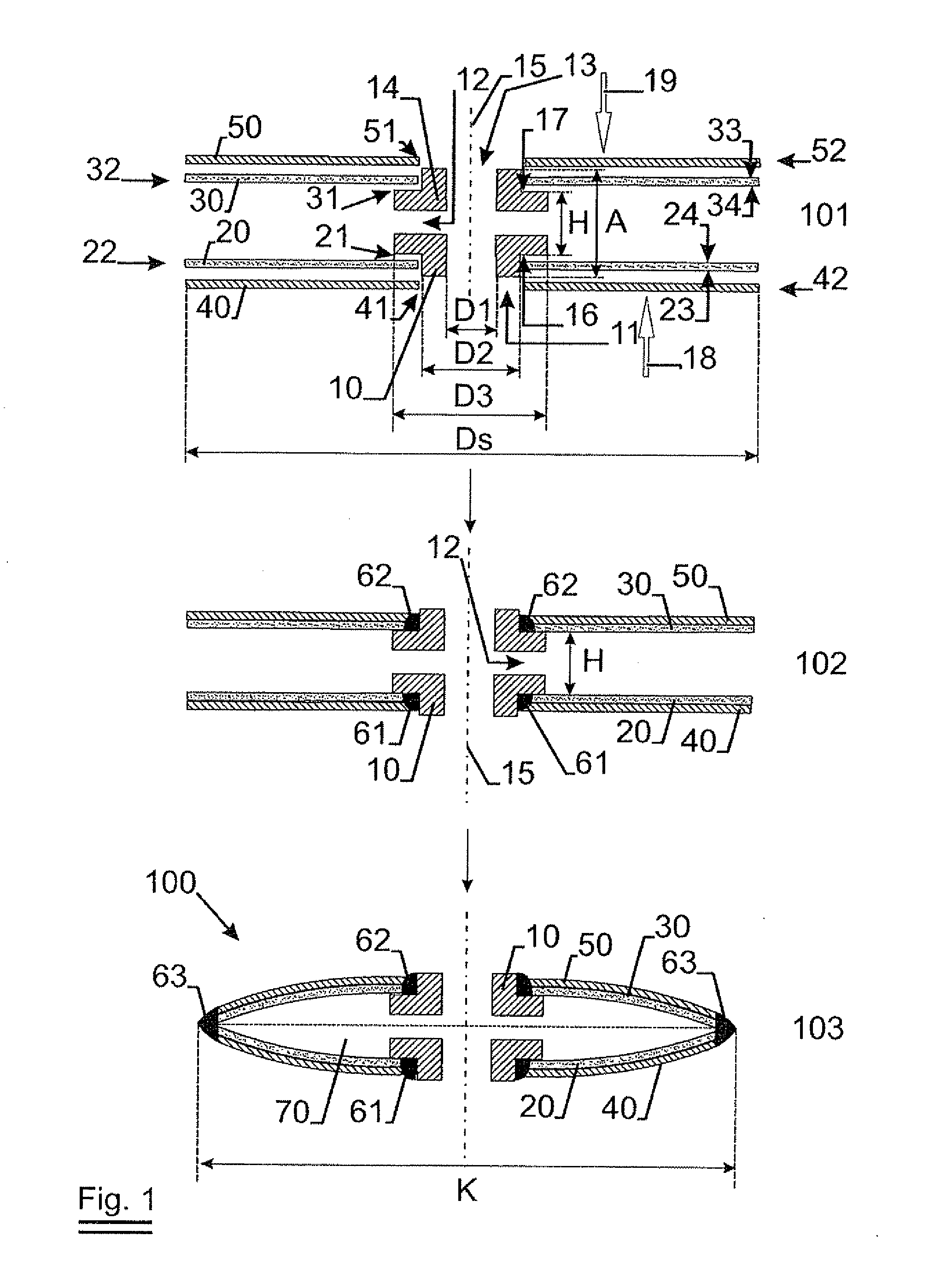
Figure 2 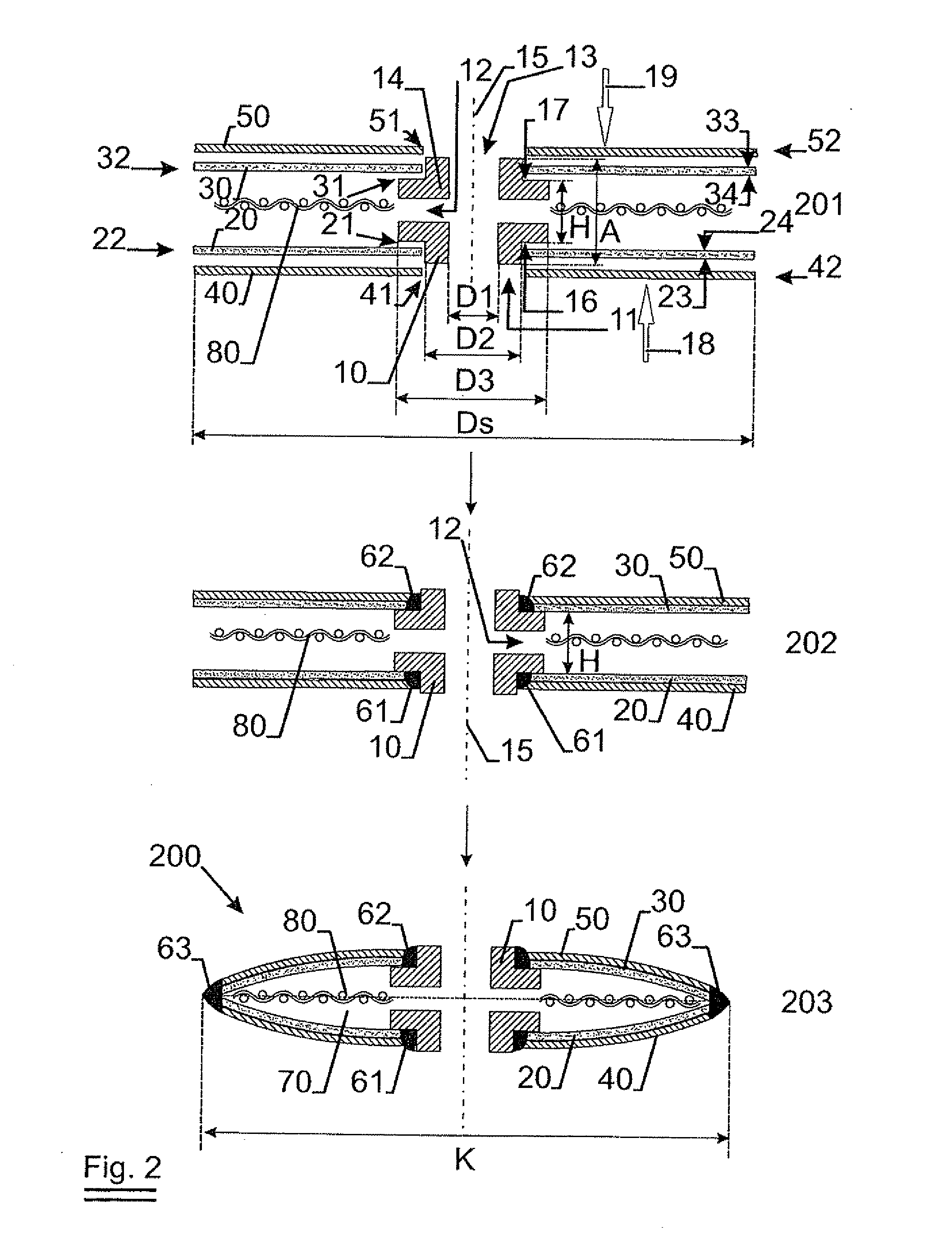
Figure 3
Abstract
Description
TECHNICAL FIELD OF THE INVENTION
[0001] The present invention relates to disc-shaped filter elements and methods to provide disc-shaped filter elements as well as devices including such disk-shaped filter elements.BACKGROUND OF THE INVENTION
[0002] Disc shaped filter elements or leaf discs are well known in the art. For example, it is known to stack several disc shaped filter elements concentrically on a perforated tube, which stack is located in a filter housing. A liquid, e.g. edible liquids such as oils, fruit juice or wines, are filtered by providing the particle loaded liquid to the outer side of the disc shaped filter elements, and discharging filtrate via the perforated tube, when the filtrate has passed though the filter membranes being part of the disc shaped filter elements.
[0003] Examples of a disc shaped filter element are described in U.S. Pat. No. 4,902,420 and U.S. Pat. No. 4,637,877. In U.S. Pat. No. 4,637,877, a disc shaped filter element comprises a hub and two filter m...
Examples
Embodiment Construction
[0061]The present invention will be described with respect to particular embodiments and with reference to certain drawings but the invention is not limited thereto but only by the claims. The drawings described are only schematic and are non-limiting. In the drawings, the size of some of the elements may be exaggerated and not drawn on scale for illustrative purposes. The dimensions and the relative dimensions do not correspond to actual reductions to practice of the invention.
[0062]Furthermore, the terms first, second, third and the like in the description and in the claims, are used for distinguishing between similar elements and not necessarily for describing a sequential or chronological order. It is to be understood that the terms so used are interchangeable under appropriate circumstances and that the embodiments of the invention described herein are capable of operation in other sequences than described or illustrated herein.
[0063]Moreover, the terms top, bottom, over, under...