
Driver circuit for driving a print head of an inkjet printer
Patent Information
- Authority / Receiving Office
- US · United States
- Current Assignee / Owner
- Publication Date
- 2011-10-27
- Estimated Expiration
- Not applicable · inactive patent
Smart Images
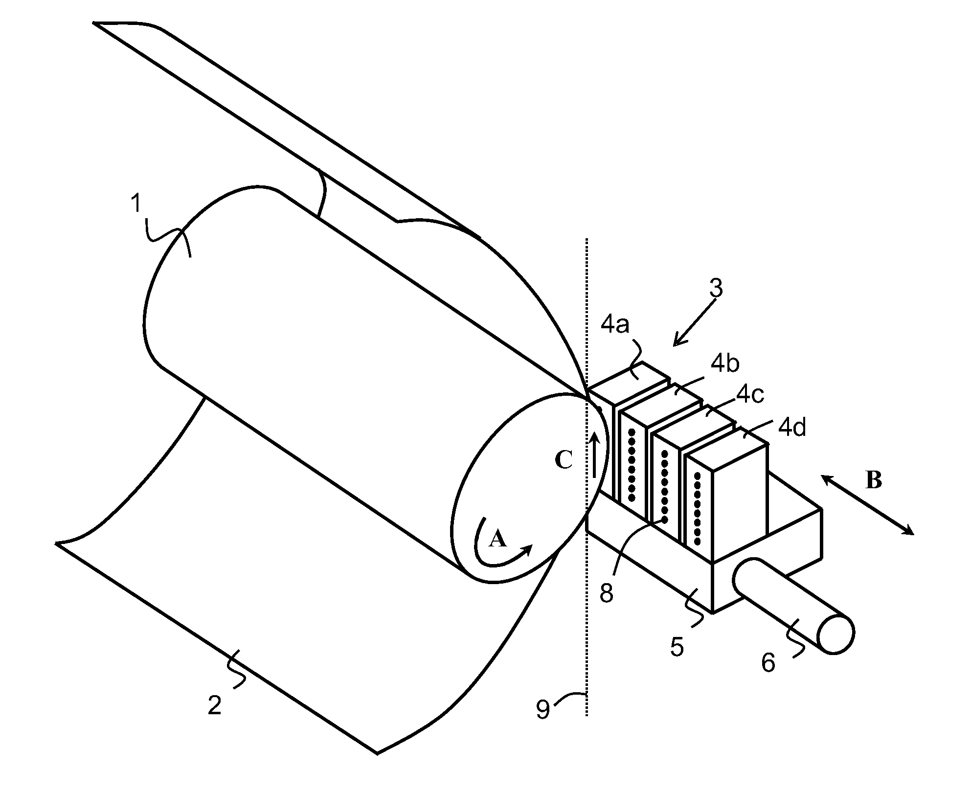
Figure 1 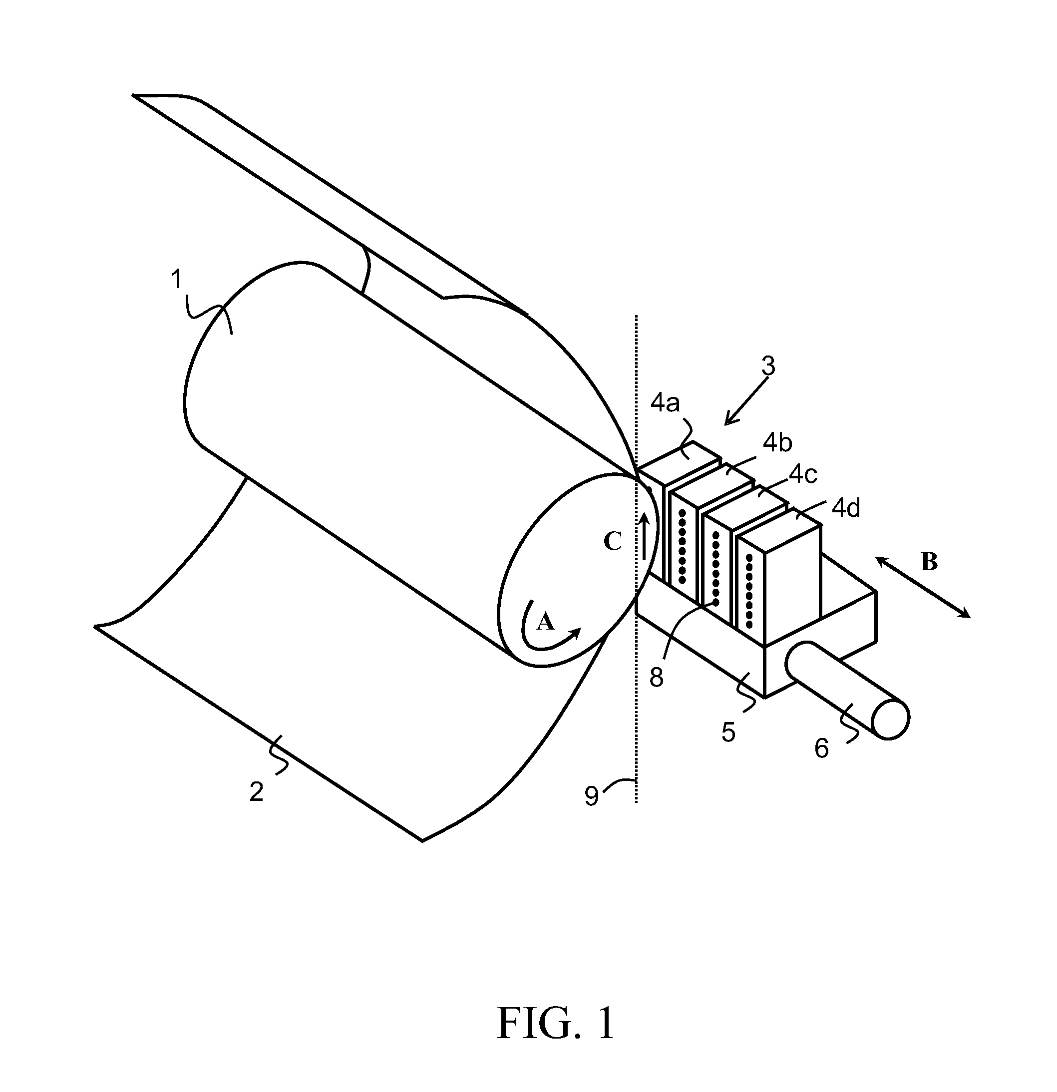
Figure 2 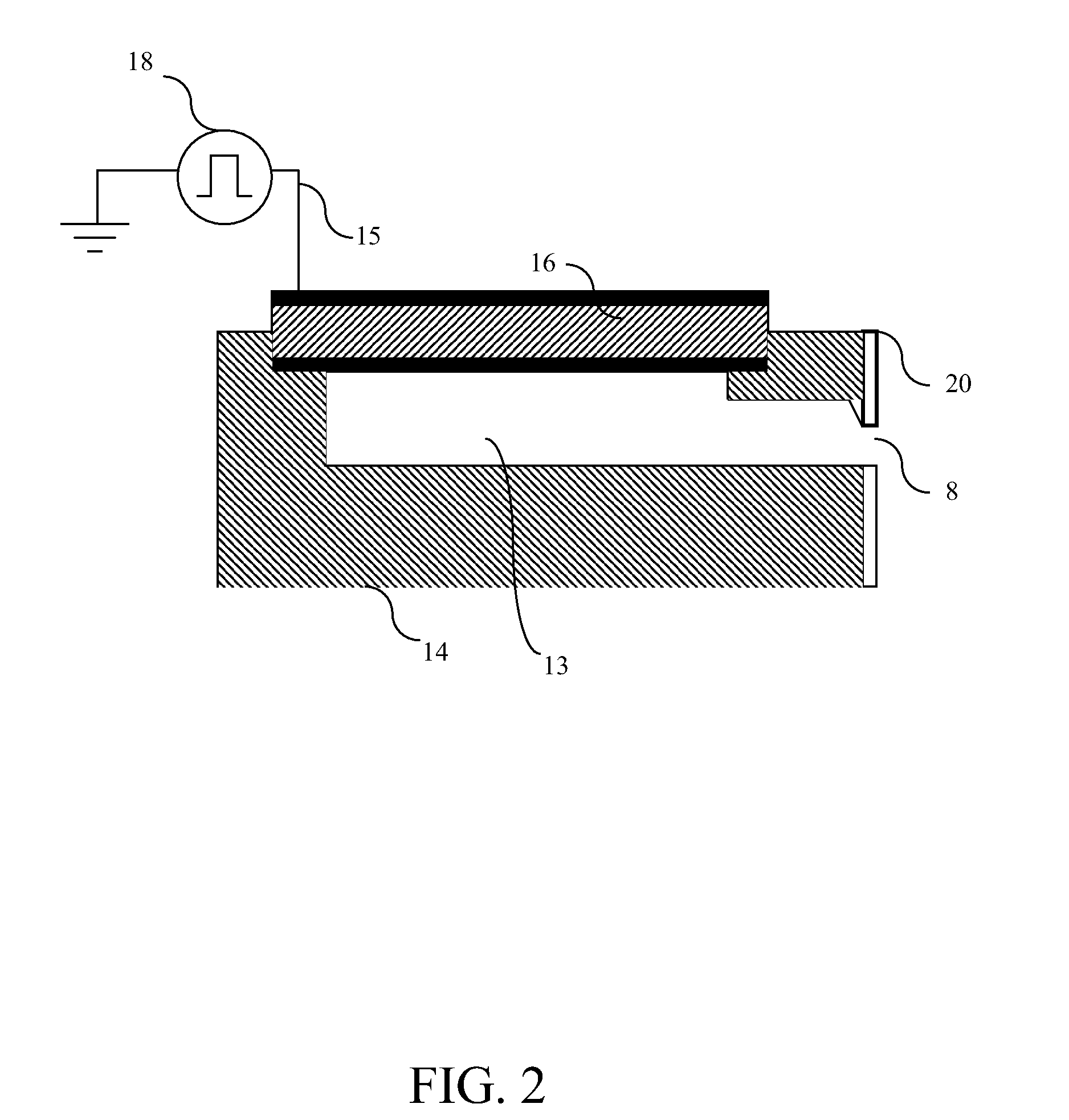
Figure 3
Abstract
Description
CROSS-REFERENCE TO RELATED APPLICATIONS
[0001] This application is a Continuation of copending PCT International Application No. PCT / EP2009 / 063894 filed on Oct. 22, 2009, which designated the United States, and on which priority is claimed under 35 U.S.C. §120. This application also claims priority under 35 U.S.C. §119(a) on Patent Application No. 08168333.6, filed in Europe on Nov. 5, 2008. The entire contents of each of the above documents is hereby incorporated by reference into the present application.BACKGROUND OF THE INVENTION
[0002] 1. Field of the Invention
[0003] The present invention relates to an inkjet printing apparatus, comprising a print head, the print head comprising an ink duct, a piezoelectric element operatively coupled to the ink duct, and a control device configured to control ink drop ejection from the ink duct by actuation of the piezoelectric element.
[0004] 2. Description of Background Art
[0005] Inkjet printers comprising piezoelectric elements are well known in the...
Examples
first embodiment
[0057]In FIG. 3, only one piezoelectric element 37 is shown. In practice, an inkjet printing apparatus may comprise a plurality of piezoelectric elements and a plurality of current sources for driving a plurality of nozzles independently. A first embodiment is shown in FIG. 5a. A number of power supplies 311, 321, 331, 341, each delivering a voltage of x V, may be connected in series to switch 351 having five input terminals 351a, 351b, 351c, 351d, 351e, outputting voltage levels 0 V, x V, 2x V, 3x V and 4x V, respectively. An output terminal of the switch 351 may be connected to a number of current sources 361a, 361n, of which a first current source 361a and a second current source 361n are shown in FIG. 5a. The current sources 361a, 361n may charge and discharge piezoelectric elements 371a, 371n, respectively, such as described above with respect to FIG. 3. A first piezoelectric element 371a and a second piezoelectric element 371n are shown in FIG. 5a. The charging of the piezoele...
second embodiment
[0058]In FIG. 5a, one switch 351 is shown. a control circuit for use with a plurality of piezoelectric elements is shown in FIG. 5b in which at least two switch 352a, 352n are arranged in the control circuit. A number of power supplies 312, 322, 332, 342, each delivering a voltage of x V, may be connected in series to the at least two switches 352a, 352n. A first switch 352a and a second switch 352n are shown in FIG. 5b. The first switch 352a is configured with five input terminals 352b, 352c, 352d, 352e, 352f, outputting voltage levels 0 V, x V, 2x V, 3x V and 4x V, respectively. The second switch 352n is configured with five input terminals 352v, 352w, 352x, 352y, 352z, outputting voltage levels 0 V, x V, 2x V, 3x V and 4x V, respectively. The first switch 352a is connected to a first current source 362a. The second switch 352n is connected to a second current source 362n. The first current source 362a may charge and discharge a first piezoelectric element 372a. The second current...