
Squeegee module
Patent Information
- Authority / Receiving Office
- US · United States
- Current Assignee / Owner
- Publication Date
- 2012-03-01
- Estimated Expiration
- Not applicable · inactive patent
Smart Images
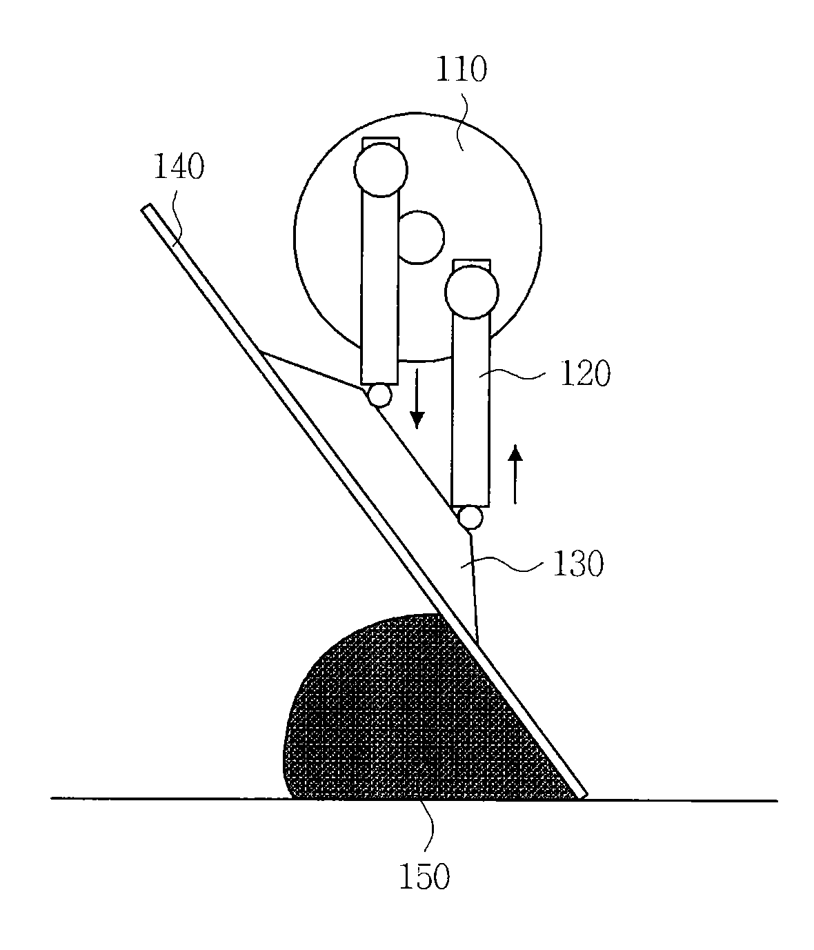
Figure 1 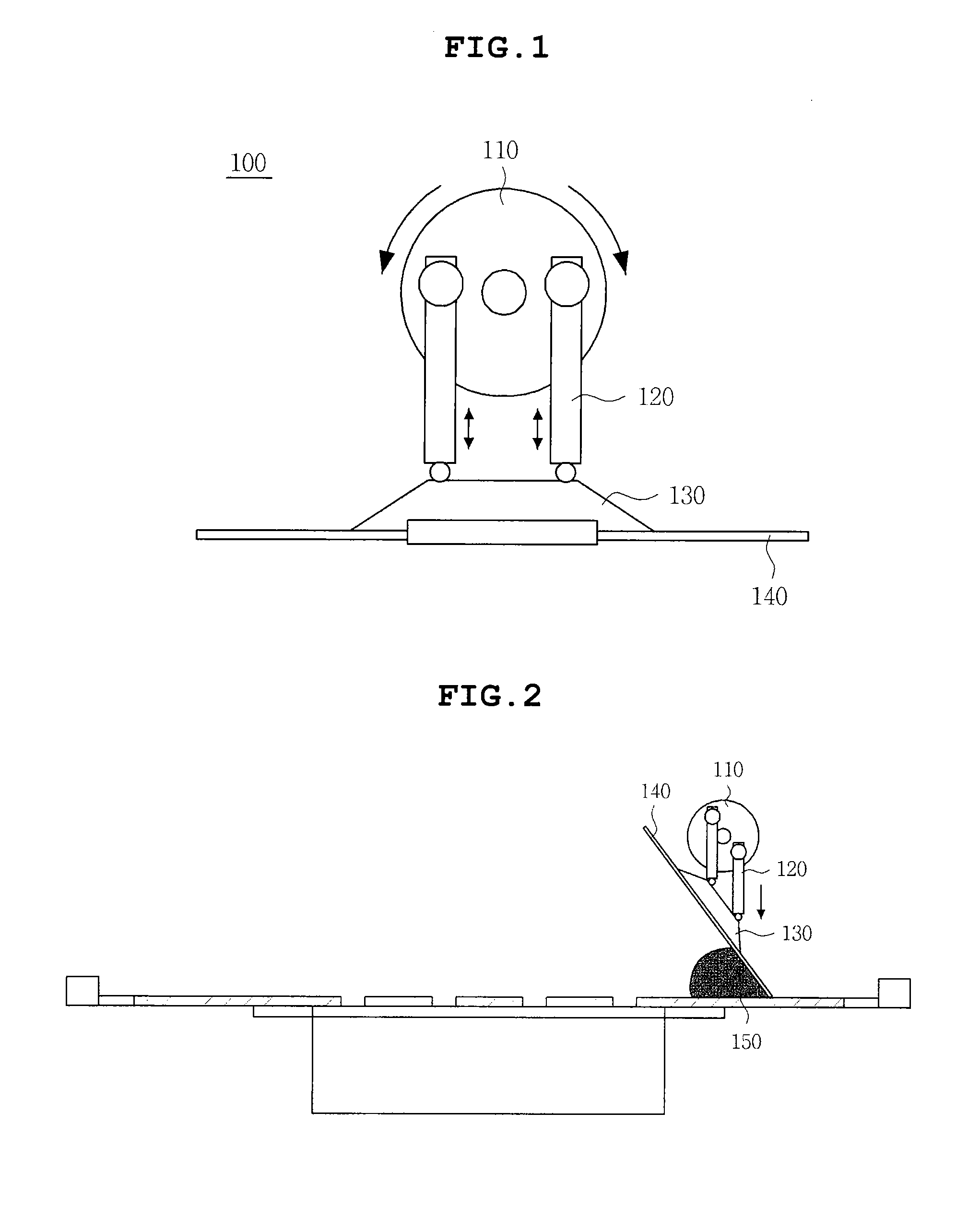
Figure 2 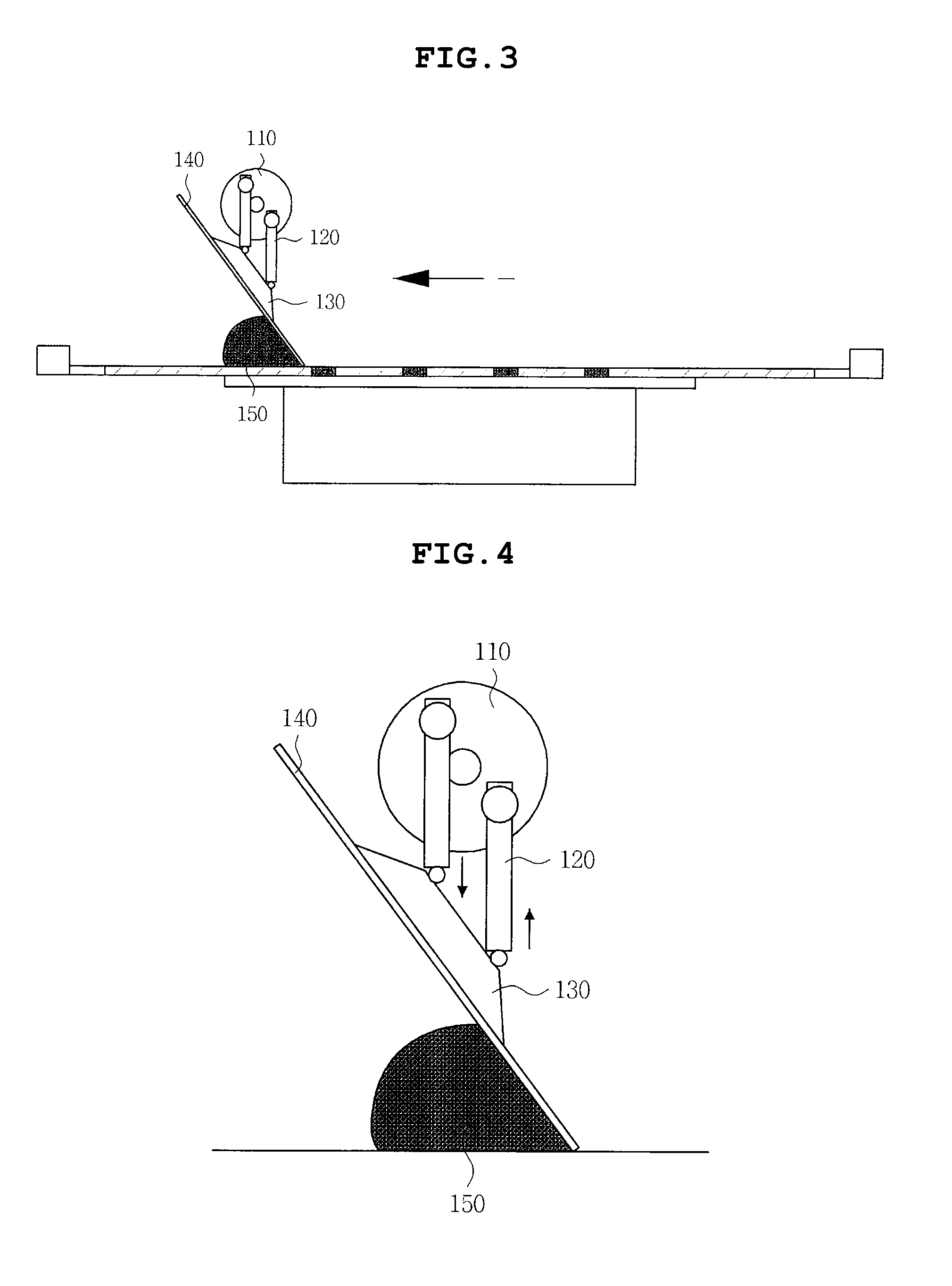
Figure 3
Abstract
Description
CROSS REFERENCE TO RELATED APPLICATION(S)
[0001] This application claims the benefit of Korean Patent Application No. 10-2010-0082955, filed on Aug. 26, 2010, entitled “Squeegee Module”, which is hereby incorporated by reference in its entirety into this application.BACKGROUND OF THE INVENTION
[0002] 1. Technical Field
[0003] The present invention relates to a squeegee module.
[0004] 2. Description of the Related Art
[0005] In recent years, developments in the electronic industry have been accompanied by stronger demands being placed on the multifunctionality and smallness of electronic elements used in electronic apparatuses. Due to the trend to multifunctionalize and miniaturize electronic elements, bump pitches, formed on integrated circuits (IC) or on substrates, are required to be ultrafine and diversified. In the related art, a variety of methods of forming bumps on the substrates are being developed and widely used. An example of the bump forming methods generally used in the related a...
Examples
Embodiment Construction
[0024]Various objects, advantages and features of the invention will become apparent from the following description of embodiments with reference to the accompanying drawings.
[0025]The terms and words used in the present specification and claims should not be interpreted as being limited to typical meanings or dictionary definitions, but should be interpreted as having meanings and concepts relevant to the technical scope of the present invention based on the rule according to which an inventor can appropriately define the concept of the terms to describe most appropriately the best method he or she knows for carrying out the invention.
[0026]The above and other objects, features and advantages of the present invention will be more clearly understood from the following detailed description taken in conjunction with the accompanying drawings. Herein, the same reference numerals are used throughout the different drawings to designate the same components. Further, when it is determined ...