
Controllable pneumatic brake booster and method for operating it
Patent Information
- Authority / Receiving Office
- US · United States
- Current Assignee / Owner
- Publication Date
- 2012-09-06
- Estimated Expiration
- Not applicable · inactive patent
Smart Images
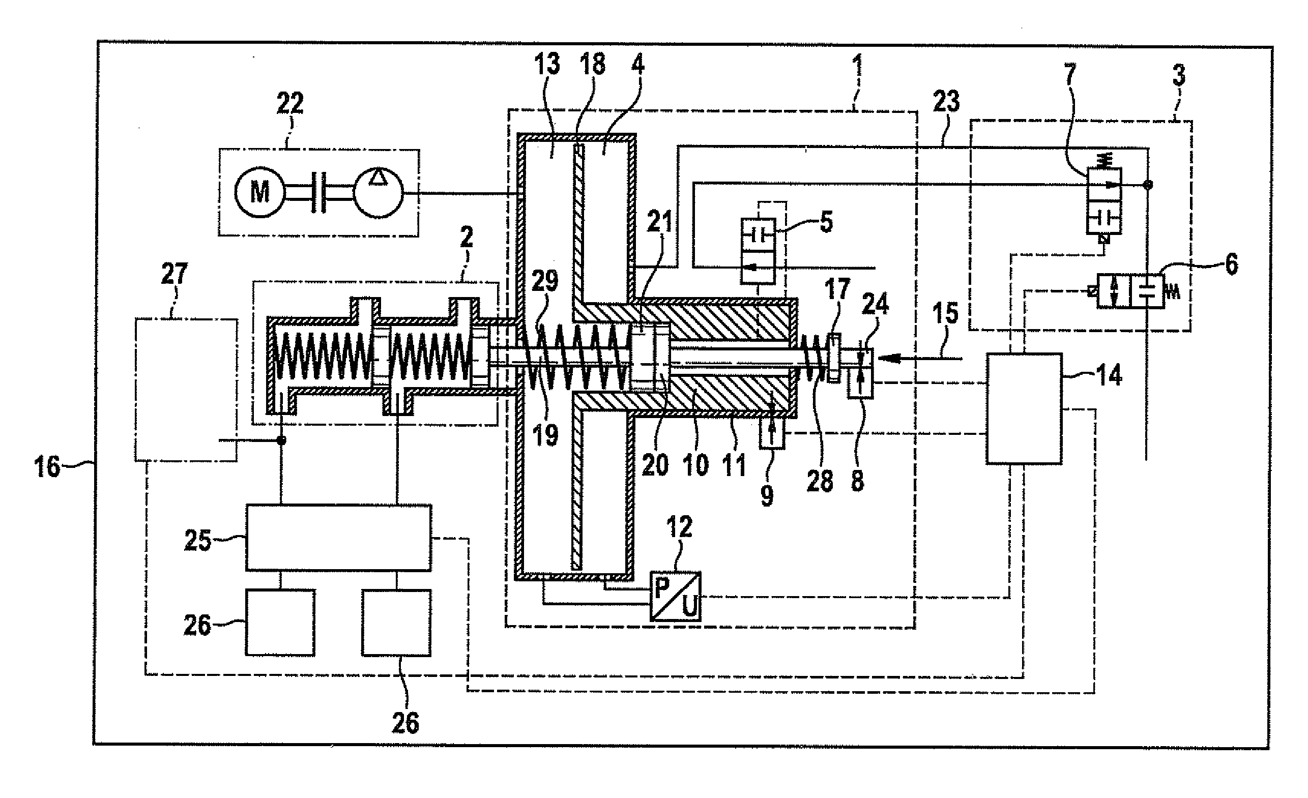
Figure 1 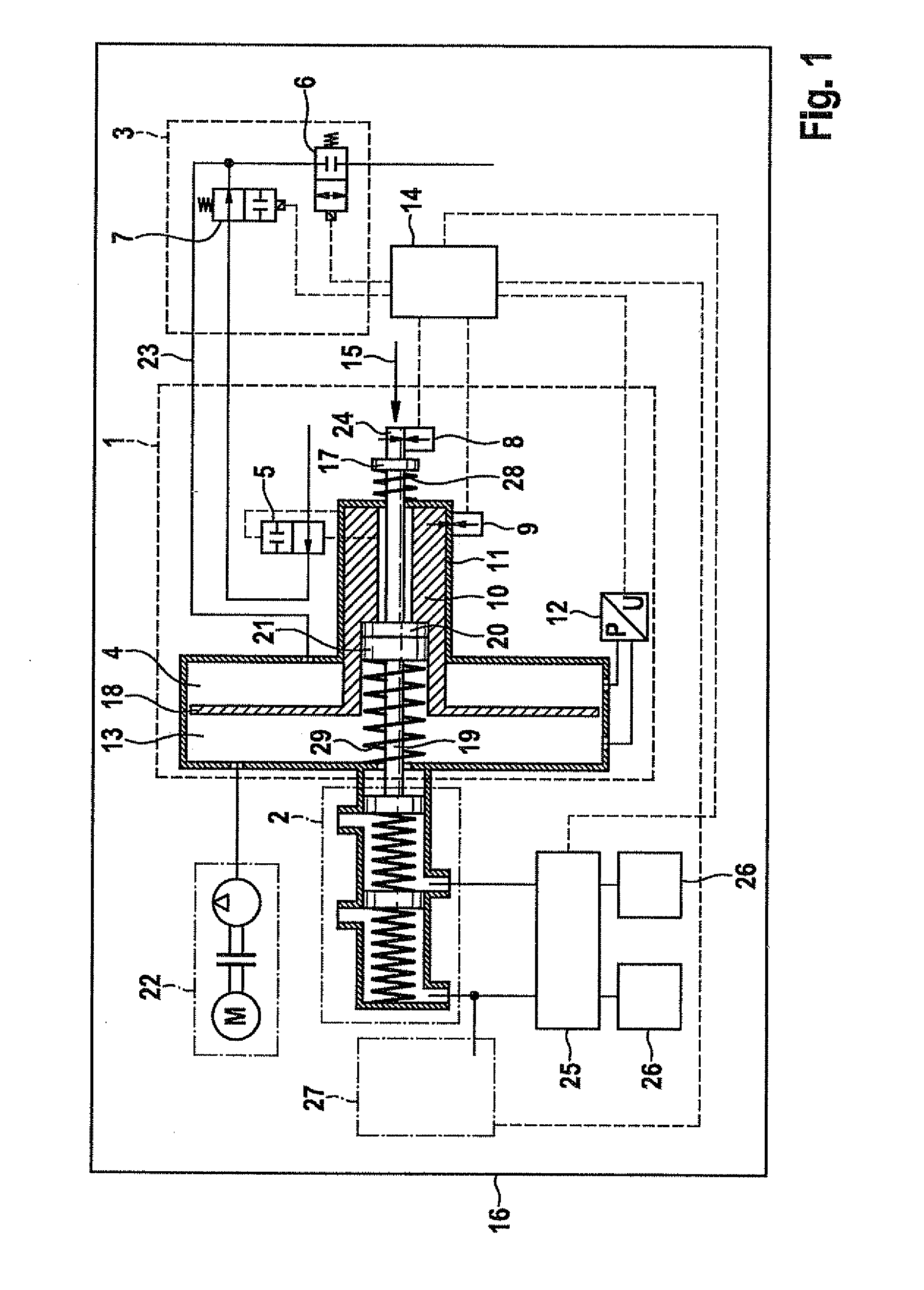
Figure 2 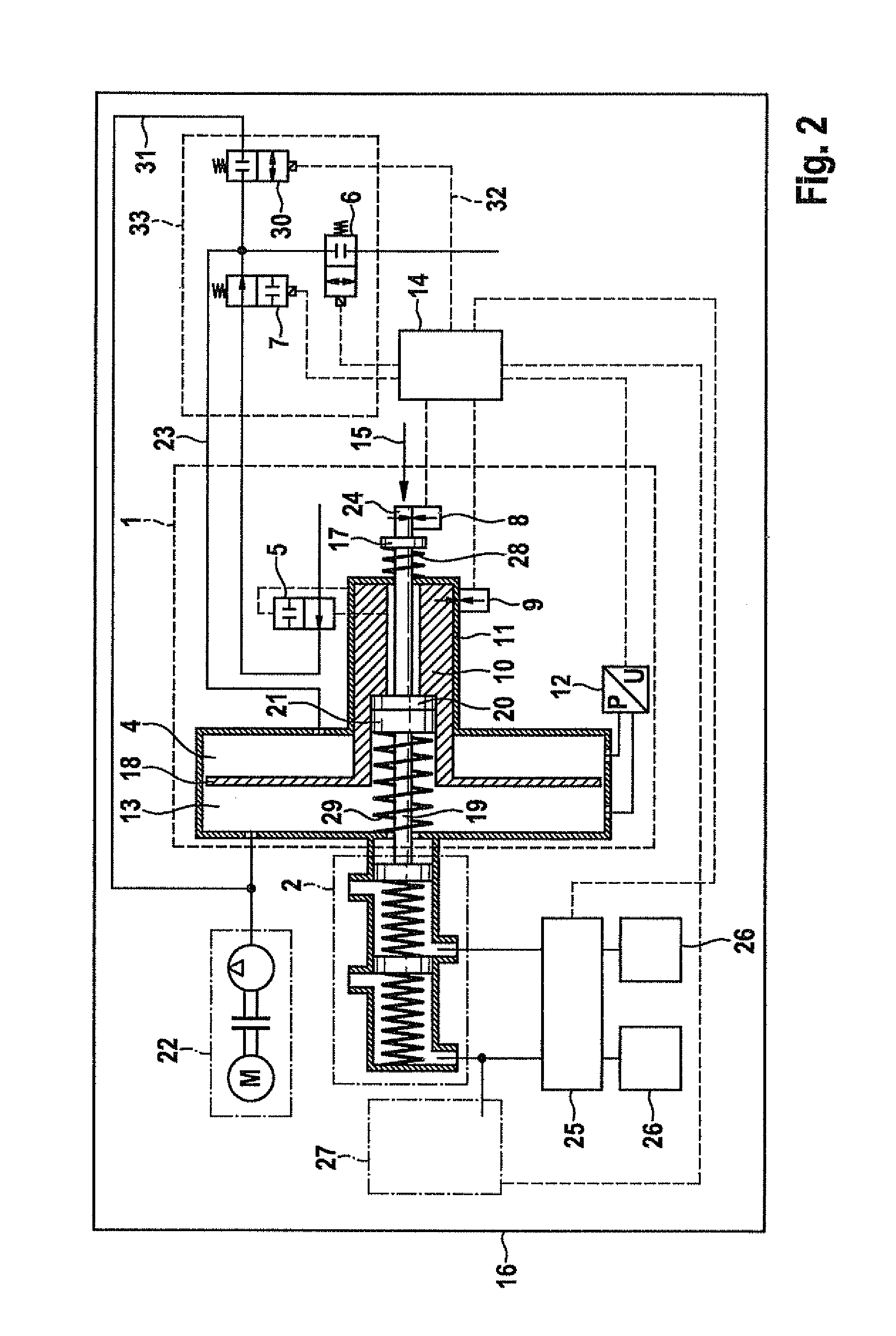
Figure 3
Abstract
Description
BACKGROUND INFORMATION
[0001] In brake systems of a vehicle, for the deceleration of the vehicle by the vehicle's driver, pressure is built up in a brake circuit via a main cylinder. To support the driver, a brake booster is able to apply an additional supporting force, if necessary. One possible specific embodiment of such a brake booster is a vacuum brake booster, as is described, for instance, in ‘Kraftfahrtechnisches Taschenbuch’ (Automotive Handbook) (25th edition, BOSCH, Vieweg Verlag ISBN 3528238763, pages 805806). An active pneumatic brake booster is also described in ‘Handbuch Fahrerassistenzsysteme’ (Handbook of Driver Assistance Systems) (2009, Vieweg+Teubner Verlag ISBN 9783834802873). This brake booster is electrically controllable, independently of the driver. In such a brake booster, the poppet valve is operated using an electrically operated magnetic drive.SUMMARY
[0002] The present invention relates to a vacuum brake booster and a method for operating the vacuum brake b...
Examples
Example
[0046]Similarly, it is possible, in the second specific embodiment, to ensure the protection from leakage of main control valve 5 or of control valve 6 via valve 30 and line 31. However, in that case, valve 30 has to be controlled by the control unit, since valve 30 is a currentless closed valve. The connection from the first chamber to vacuum supply 22 goes via line 23.
[0047]In general, a connection of main control valve 5 and of control valve 6 to vacuum supply 22 is possible both via valve 30 and valve 34, as well as via both valves at the same time.
[0048]Because of the possibility of setting the supporting force of the brake booster via adjusting device 3, the brake booster 1 may be used in an overall brake system which, besides the hydraulic brake system includes an additional brake system such as a regenerative brake subsystem. When the proportion of the regenerative brake subsystem of the overall braking effect changes, the braking effect of the hydraulic brake system has to ...