
System for sealing a shaft
Patent Information
- Authority / Receiving Office
- US · United States
- Current Assignee / Owner
- Publication Date
- 2013-04-18
- Estimated Expiration
- Not applicable · inactive patent
Smart Images
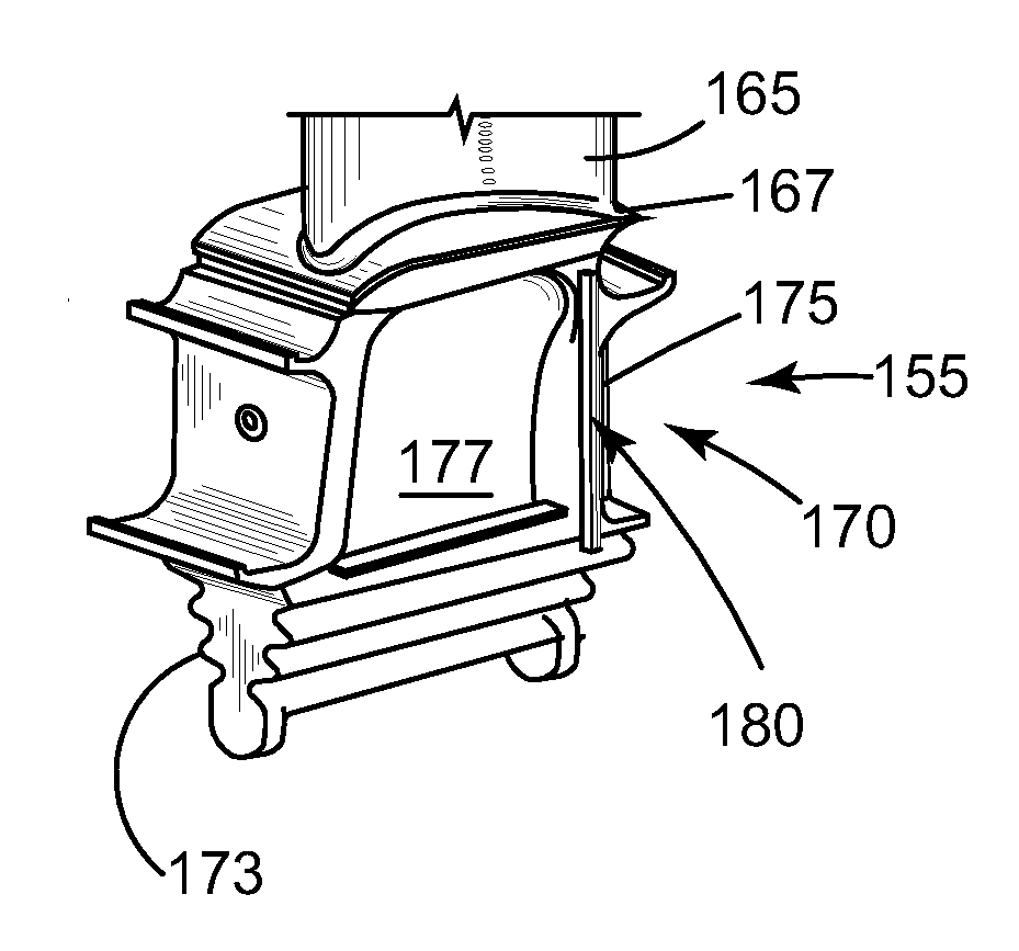
Figure 1 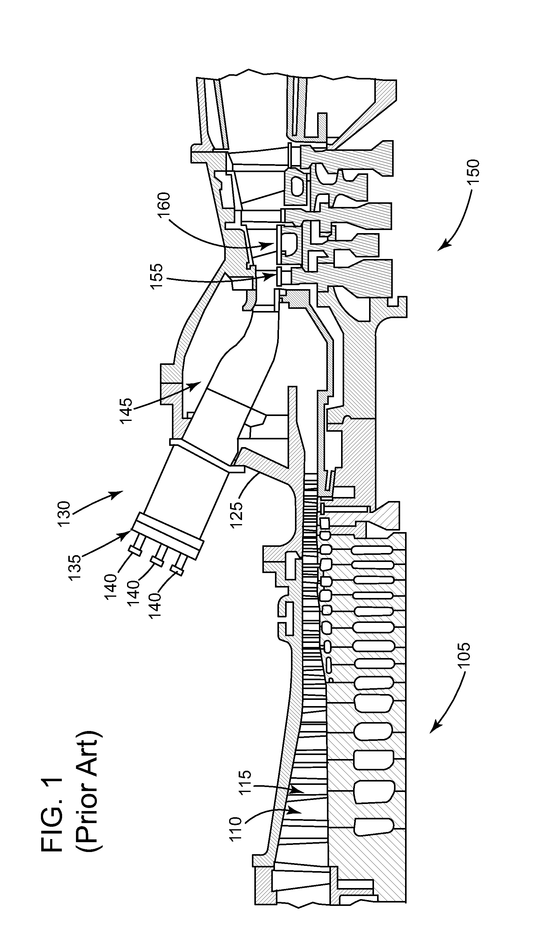
Figure 2 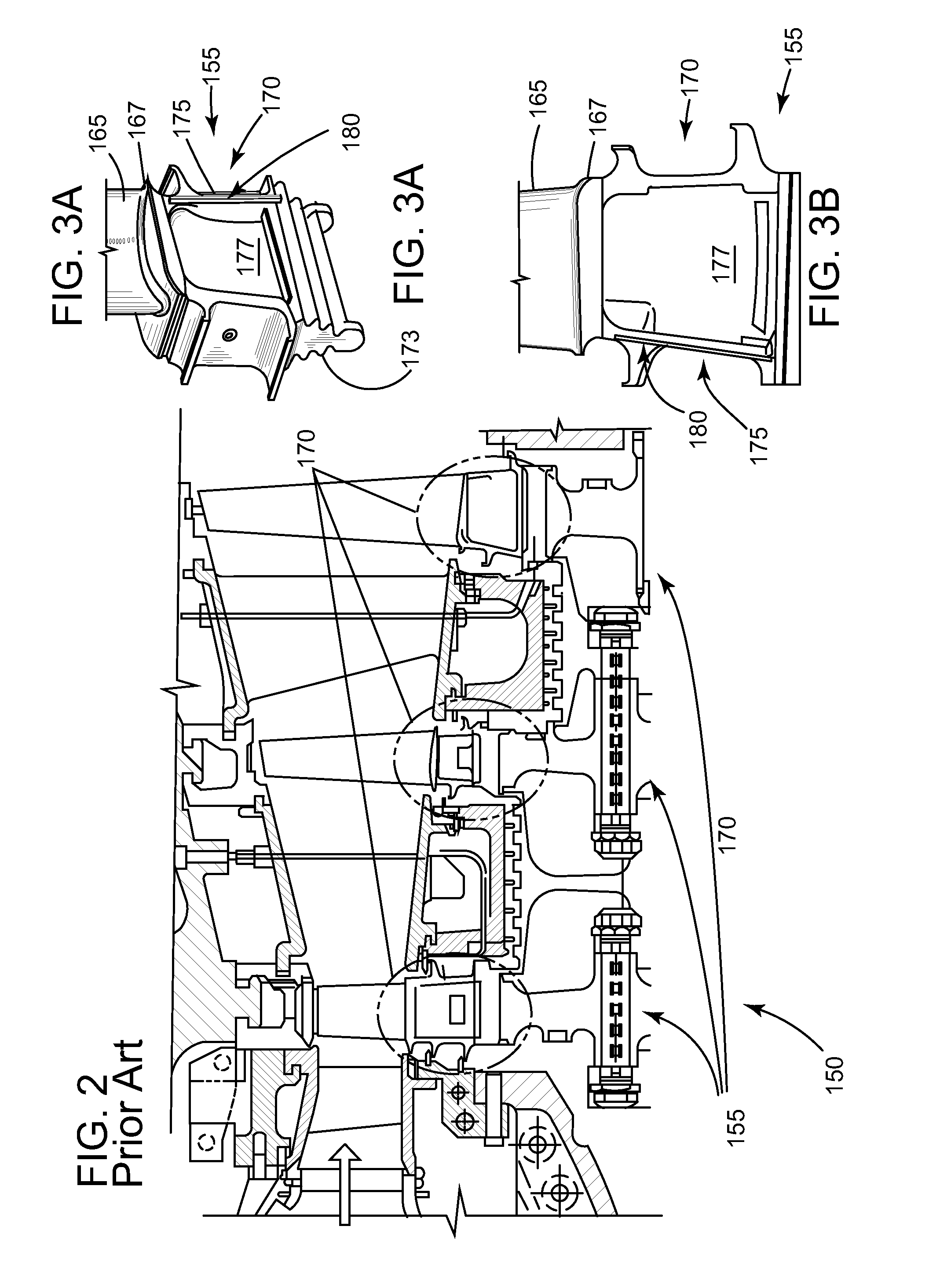
Figure 3
Abstract
Description
BACKGROUND OF THE INVENTION
[0001] The present invention relates to seals for air-ingesting turbomachines; and more particularly to a seal for the shank region of a rotating component of the turbomachine.
[0002] Conventional turbomachines includes compressor and turbine sections that each has a plurality of rotating components (compressor blades, turbine components, etc) attached about a circumference of a turbine rotor. Each rotating component is located at a distance away from an adjacent rotating component to allow movement and expansion during operation. Each rotatable component includes: a shank that attaches to the rotor, a platform, and an airfoil that extends radially outwardly from the platform.
[0003] The area between the adjacent rotating components is considered the shank pocket. Generally, the cavities between the rotating components and adjacent stationary components forward and aft of the shank pocket are at different operating pressures. Fluid naturally flows from the high...
Examples
Embodiment Construction
[0016]One or more specific embodiments of the present invention will be described below. In an effort to provide a concise description of these embodiments, all features of an actual implementation may not be described in the specification. It should be appreciated that in the development of any such actual implementation, as in an engineering or design project, numerous implementation-specific decisions are made to achieve the specific goals, such as compliance with system-related and / or business-related constraints, which may vary from one implementation to another. Moreover, it should be appreciated that such effort might be complex and time consuming, but would nevertheless be a routine undertaking of design, fabrication, and manufacture for those of ordinary skill having the benefit of this disclosure.
[0017]Detailed example embodiments are disclosed herein. However, specific structural and functional details disclosed herein are merely representative for purposes of describing ...