
Pneumatic parts feeder
Patent Information
- Authority / Receiving Office
- US · United States
- Current Assignee / Owner
- Publication Date
- 2015-02-12
- Estimated Expiration
- Not applicable · inactive patent
Smart Images
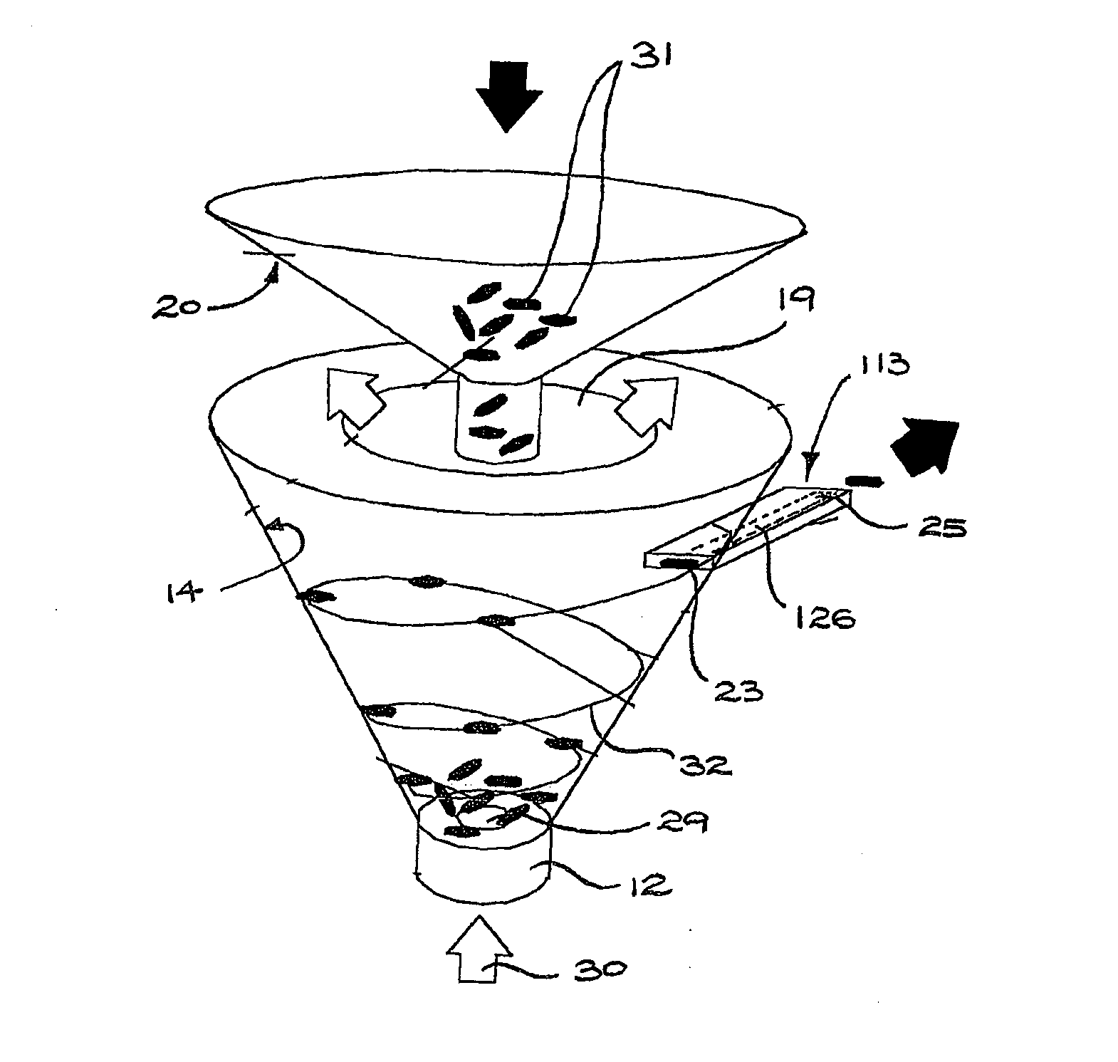
Figure 1 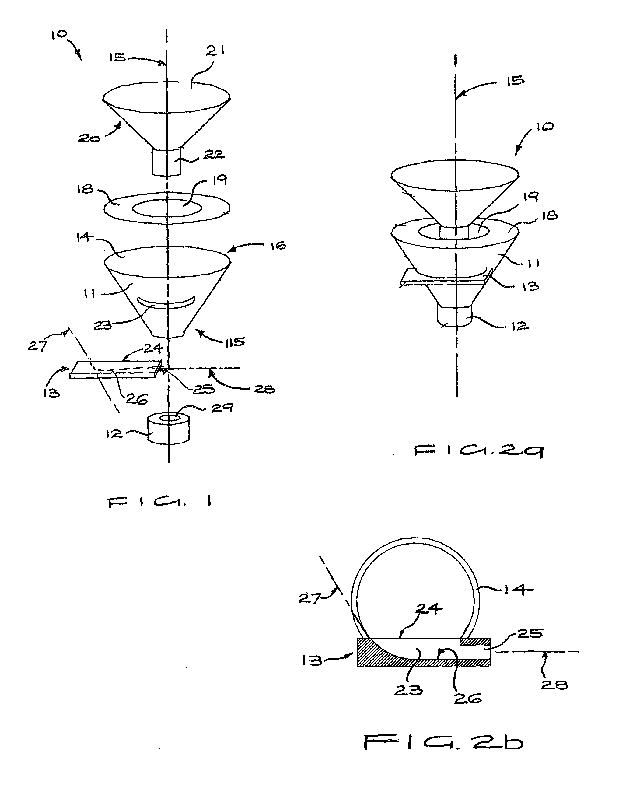
Figure 2 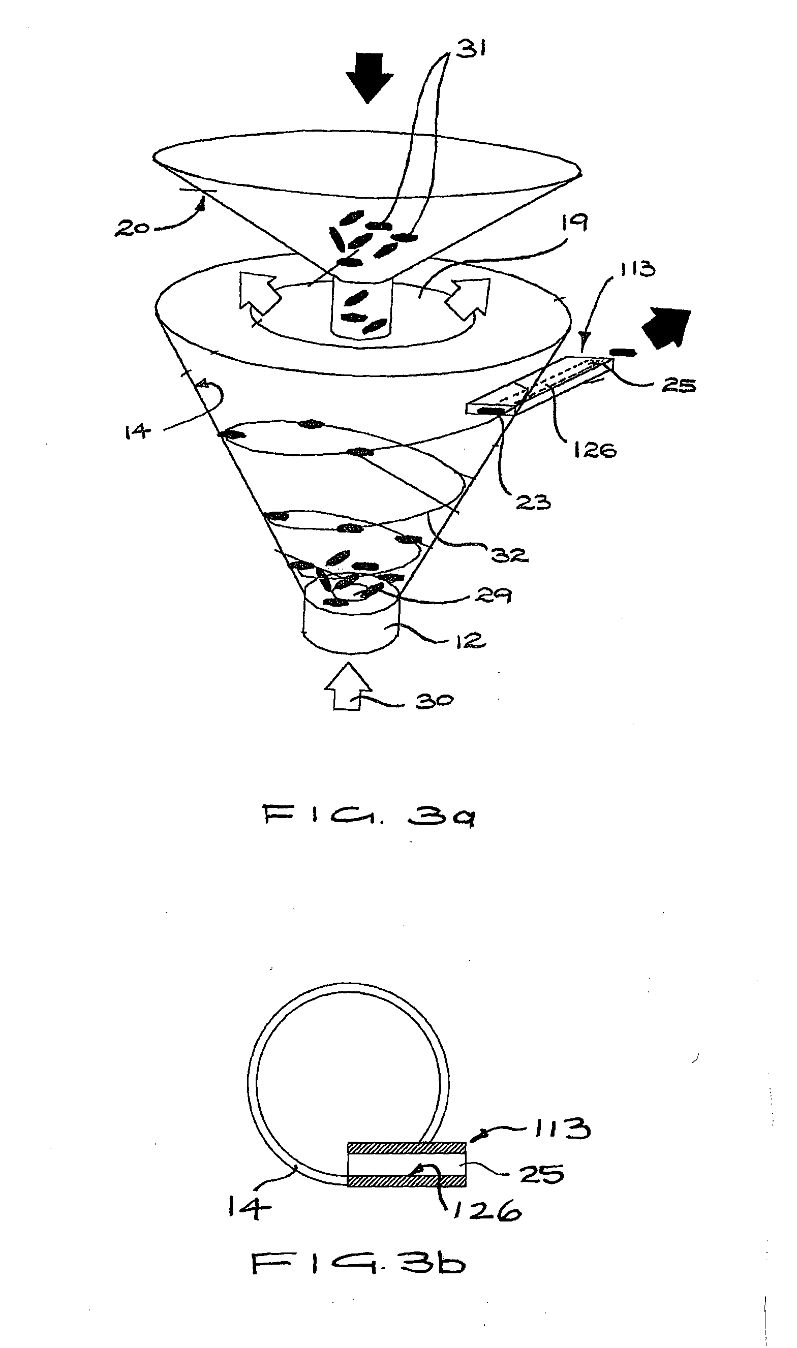
Figure 3
Abstract
Description
TECHNICAL FIELD
[0001] The present invention relates to pneumatic parts feeders for separating, orienting and continuously feeding parts, and particularly to parts feeders in which a circulating air flow or vortex is generated.BACKGROUND OF THE INVENTION
[0002] Devices are known which take parts such as springs or O-rings, and the like, and separate or untangle and orient the parts in a predetermined manner, facilitating use of the parts in subsequent manufacturing operations.
[0003] The patent publication DE102008054106 describes a pneumatic parts feeder comprising a cylinder in which a vortex is induced by tangentially aligned air inlets near the lower end of the cylinder and a helical rib provided on the cylindrical wall. The vortex entrains the parts, which are thereby singularised and rise up the helical rib toward an outlet near the top of the cylinder.
[0004] The publication DE4442337 describes a pneumatic parts feeder comprising a conical bowl in which a vortex is induced by a tang...
Examples
first embodiment
[0035]Referring to FIGS. 1, 2a and 2b, a parts feeder 10 according to the invention generally includes a vortex chamber 11, a vortex generator 12 and an outlet part 13. The vortex chamber 11 has a wall 14 which is rotationally symmetric about an axis 15. As used herein, the term “axial” refers to a direction substantially parallel to the axis 4. As illustrated, the wall 14 may be frusto-conical with a circular cross section, tapering in the axial direction between a narrow end 115 and a broad end 16. Circular rims of the ends 115, 16 may lie in respective parallel planes transverse to the axis 15. A slotted outlet port 23 may be provided in the wall 14 intermediate the ends 115, 16 and sized to removeably receive the outlet part 13, which may have a bar-like form. An annular wall 18 of planar form may be fixed to the broad end 16 so as to form an inwardly projecting lip bounding a central aperture 19 from which air may escape the vortex chamber. Holes (not shown) may be provided in ...
second embodiment
[0039]The operation of the parts feeder is described below with respect to a second embodiment shown in FIGS. 3a and 3b, which differs from the parts feeder of FIGS. 1, 2a and 2b only in respect of the outlet part 113. Rather than being curved, the outlet channel 126 (indicated by dashed lines in FIG. 3) is straight, and extends linearly between the part outlet port 23 and the aperture 25, which are at longitudinally opposing ends of the outlet part 113. Air flow from an air supply (not shown) such as a fan, compressor or reservoir of compressed air is indicated by arrow 30 and is supplied to the vortex generator 12. Bulk parts 31, such as O-rings or springs, dropped into the vortex chamber 11 through the funnel 20 fall to the narrow end 115 where they are entrained in a vortex and are thereby separated from one another and orientated. The major part of this circulating air flow exits the vortex chamber 11 through the annular section of central aperture 19 about the stem 22. The par...