
Method and apparatus for imparting false twist to yarn before ring spinning
Patent Information
- Authority / Receiving Office
- US · United States
- Current Assignee / Owner
- Publication Date
- 2013-10-03
Smart Images
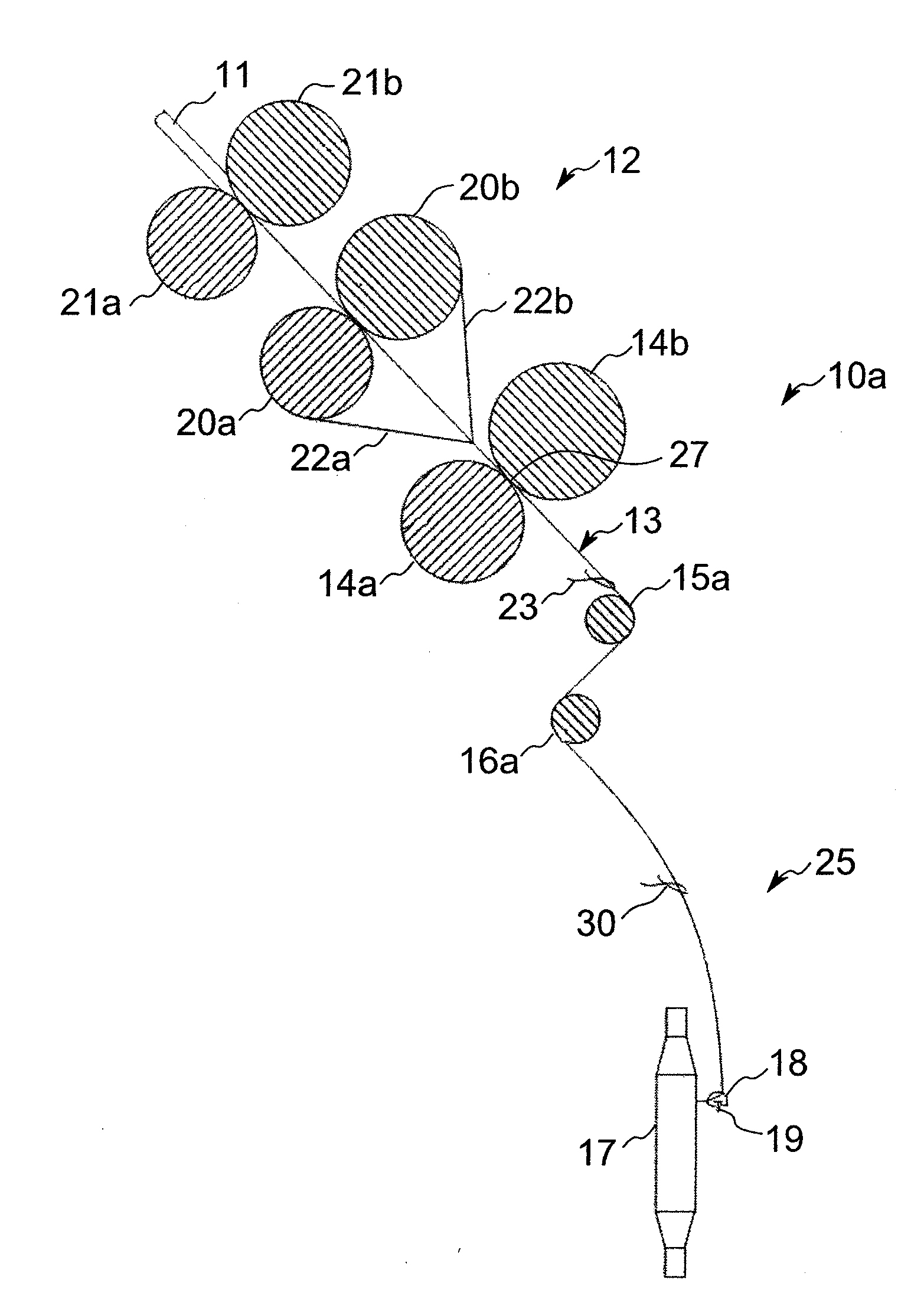
Figure 1 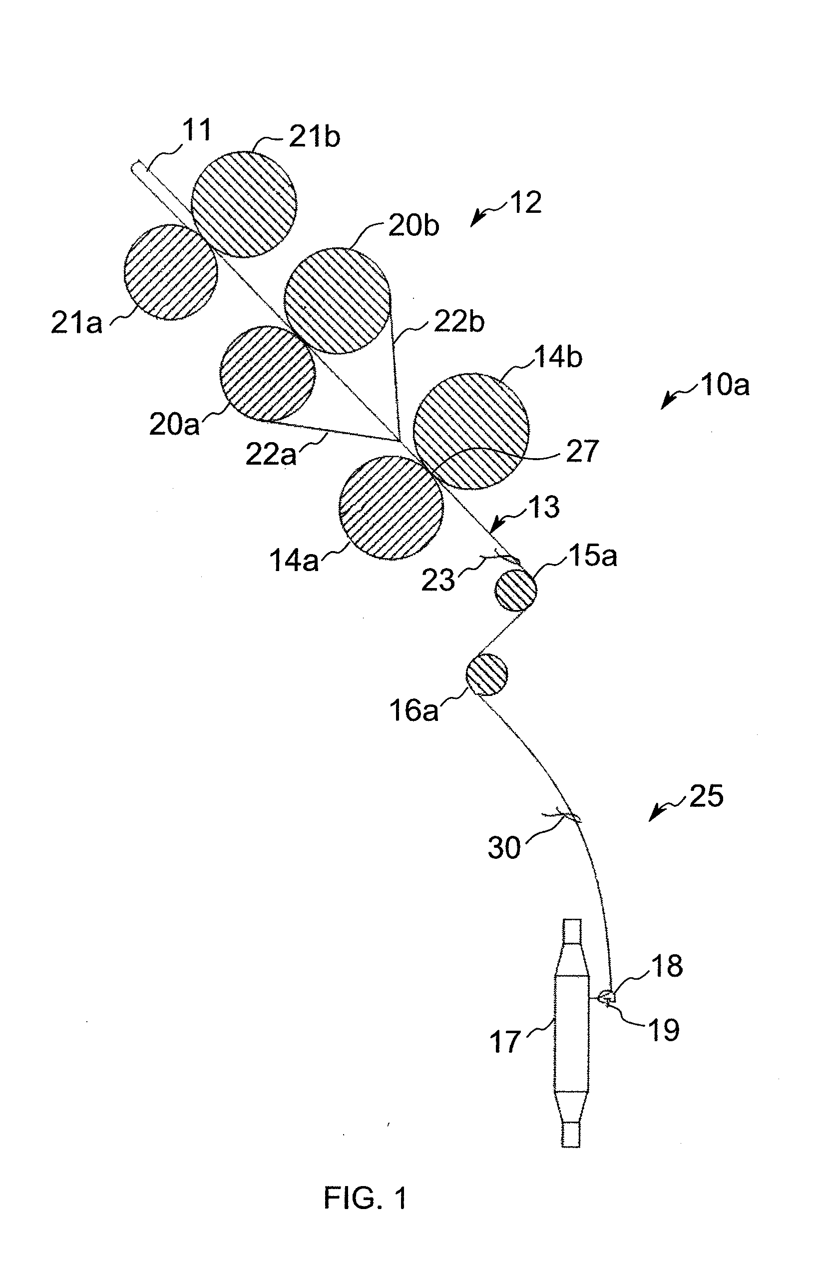
Figure 2 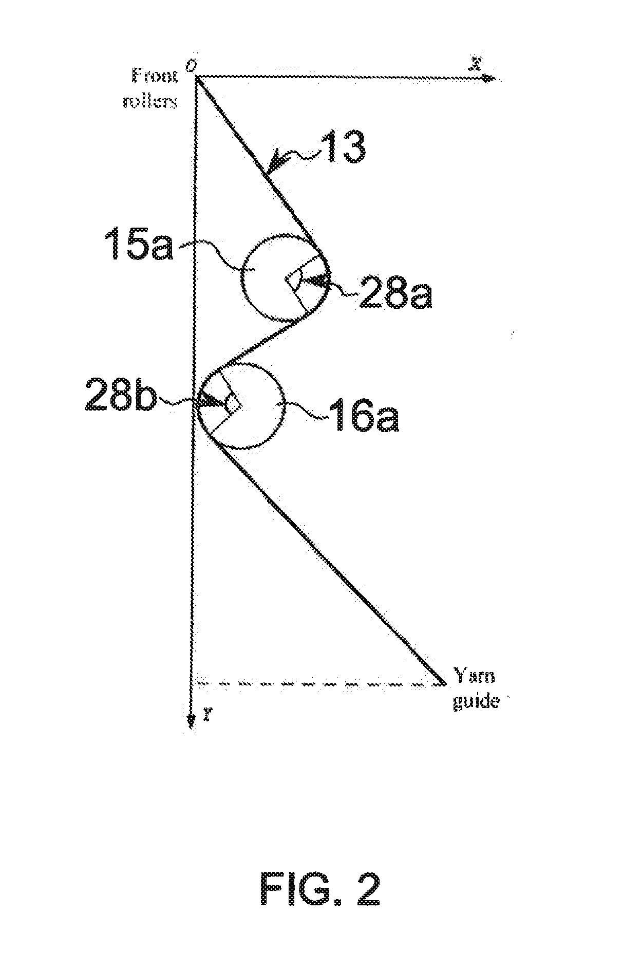
Figure 3
Abstract
Description
TECHNICAL FIELD
[0001] The present invention relates to yarn manufacture by ring spinning, and more particularly to a method and apparatus for imparting false twist to a yarn delivered from a nip of a pair of front drafting rollers immediately before imparting real twist by ring spinning.BACKGROUND OF THE INVENTION
[0002] The characteristics of ring spun yarn are unmatched by the products of other yarn spinning techniques which may be more productive, so it is a technology that is unlikely to be superseded in the near term. Much research has gone into ring spinning technology and relatively modest improvements to the productivity of a ring spinning frame can be very significant in a spinning mill where many thousands of spindles are employed. Many different raw material and machine-related factors directly influence both productivity and quality, and sometimes improvements in one area have consequences that necessitate a trade-off in another area. The goal of spinning technologists mig...
Examples
Embodiment Construction
[0021]In machines 10a and 10b (shown in FIGS. 1 and 5 respectively) for spinning short staple fibres (those less than 2 inches or approximately 50 mm in length) the roving 11 (the precursor to the yarn 13) is fed into a drafting system 12 where it is drawn to its final count. The exemplary drafting system 12 is shown at an angle of 45° to the horizontal and may comprise a six-roller, double-apron drafting system. After the resulting thin ribbon of fibres leaves the delivery or front rollers 14, false twist is applied by the upper and lower linear runs 15a, 16a of two travelling endless belts 15, 16. The twist necessary for imparting strength is provided, in a direction opposite the false twist, by the take-up assembly 25 which also serves to draw the yarn 13 across the upper and lower linear runs 15a, 16a. The take-up assembly 25 is of conventional construction and includes the bobbin 17 rotating at high speed on a spindle. In the process each rotation of the traveller 18 on the spi...