
Direct conversion receiver having a low pass pole implemented with an active low pass filter
a low-pass filter and receiver technology, applied in the field of direct conversion rf receivers, can solve the problems of increasing fabrication/testing complexity, increasing cost, and inability to make large ohmic values of rb>1/b> and rb>3/b>, so as to reduce component count and cost, and increase reliability
Patent Information
- Authority / Receiving Office
- US · United States
- Current Assignee / Owner
- Publication Date
- 2006-06-13
Smart Images
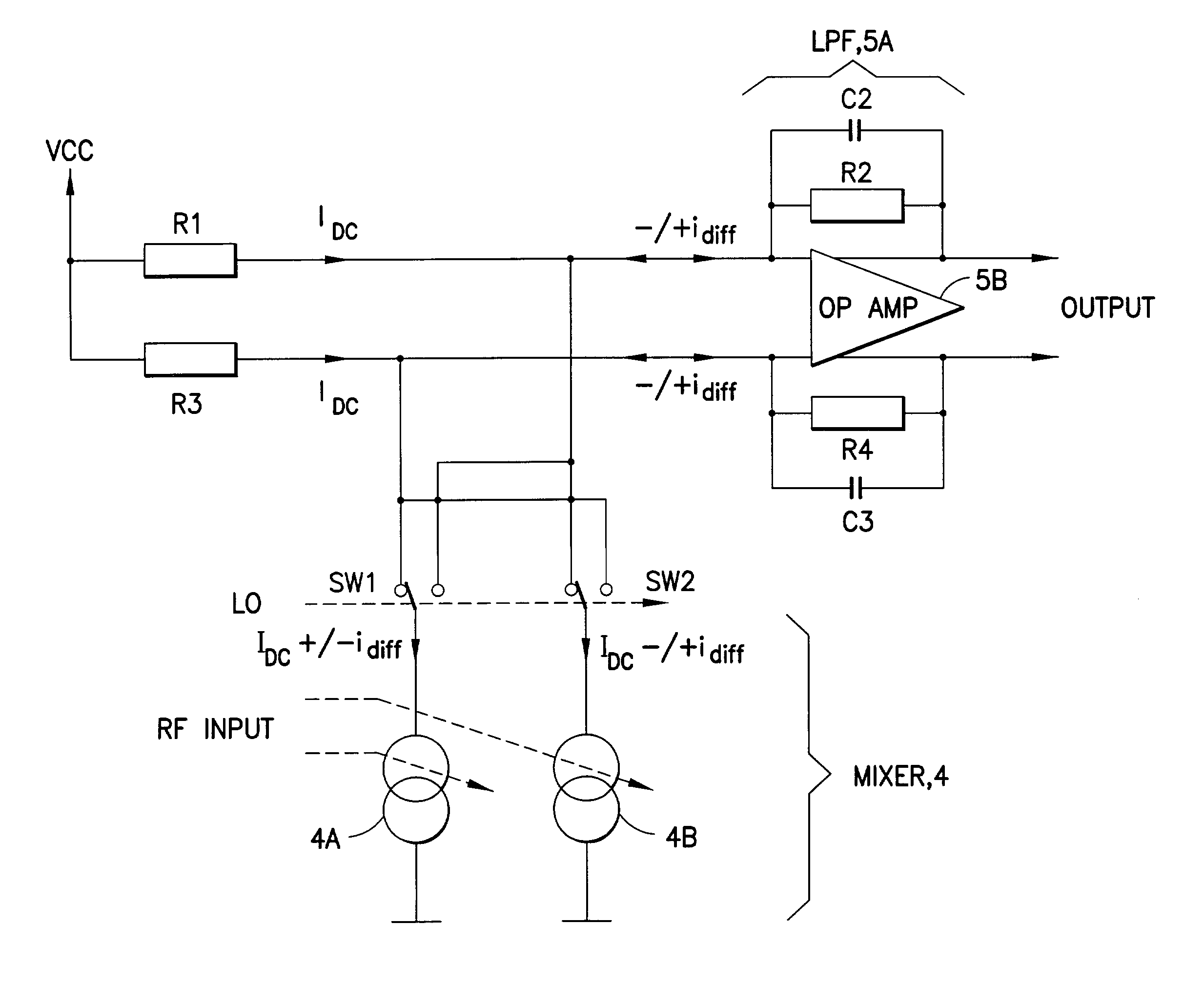
Figure 1 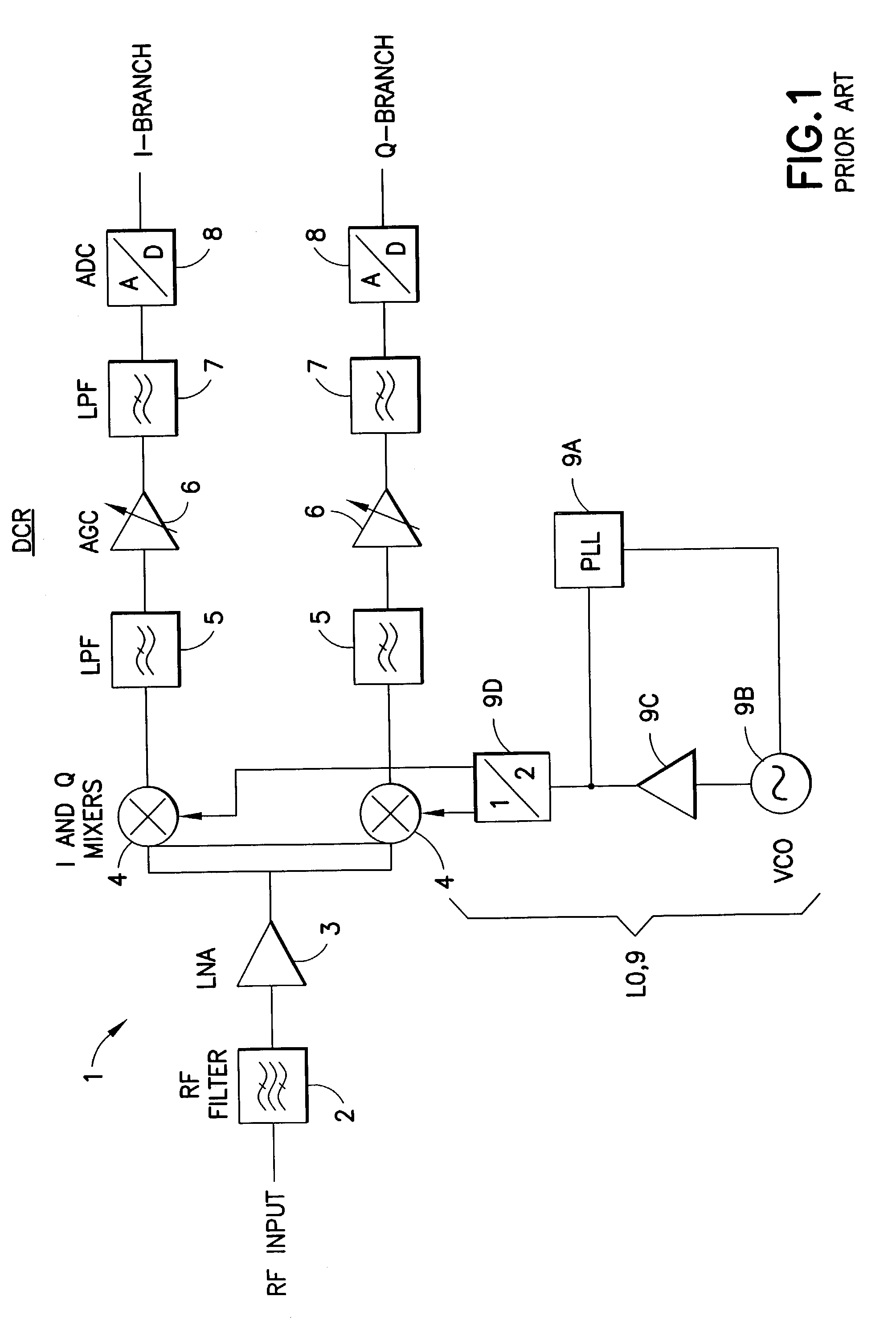
Figure 2 
Figure 3
Abstract
Description
TECHNICAL FIELD
[0001] The teachings of this invention relate generally to radio frequency (RF) receivers and, more specifically, relate to direct conversion RF receivers and to mixers used with direct conversion RF receivers.BACKGROUND
[0002] Direct conversion RF receivers, or more simply direct conversion receivers (DCRs), have been found to be attractive for use in mass produced consumer communication products such as cellular telephones and personal communicators. This is due to the fact that the DCR has a relatively simple structure (as compared to the conventional heterodyne or superheterodyne type of receiver), a reduced component count, and enables a high level of circuit integration to be achieved. The DCR is so-named because the received RF frequency is down-mixed or down-converted directly to a DC baseband signal, or to a very low frequency baseband signal, without undergoing one or more stages of intermediate frequency (IF) down-mixing.
[0003] FIG. 1 is a simplified schematic ...
Examples
Embodiment Construction
[0024]Reference is now made to FIG. 3 for showing a simplified schematic diagram of an embodiment of the mixer 5 and an improved low pass filter 5A in accordance with the teachings of this invention. The output currents from the mixer core 4 are connected to the virtual ground node of the operational amplifier (op amp)5B. Because of feedback both inputs to the op amp 5B are at the same DC potential, and differential currents are forced to go through the feedback circuitry. However, common mode DC currents can also be supplied by R1 and R3. This is preferred, as it means that the comer frequency of the low pass pole is not affected by the values of R1 and R3. As such, their values can be made small, thereby producing a low DC voltage drop from the supply voltage VCC.
[0025]In this embodiment the low pass pole of the LPF is implemented not by the passive LP filter comprised of R1, R3 and C1, but instead by an active LP filter comprised of the operational amplifier 5B in combination wit...