
Cup impactor
a technology of impactor and cup, which is applied in the field of surgical cup impactor, can solve the problems of patient inconvenience and considerable strain
Patent Information
- Authority / Receiving Office
- US · United States
- Patent Type
- Applications(United States)
- Current Assignee / Owner
- Publication Date
- 2018-05-31
Smart Images
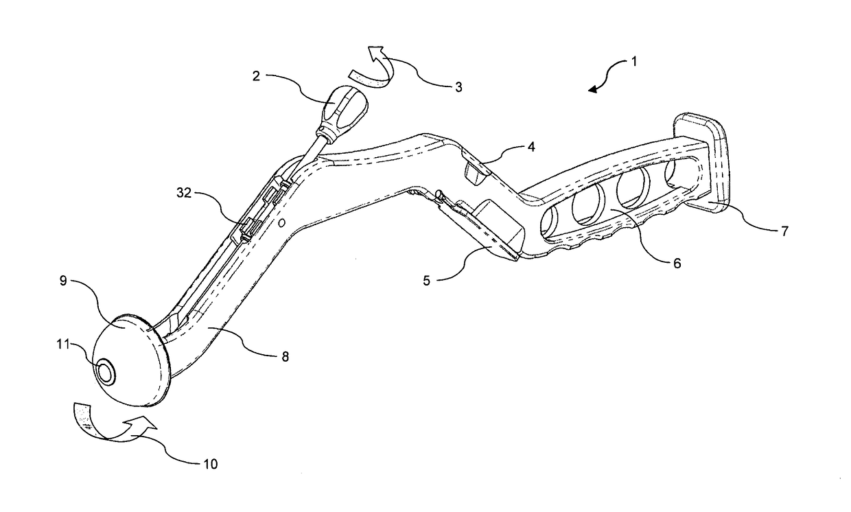
Figure 1 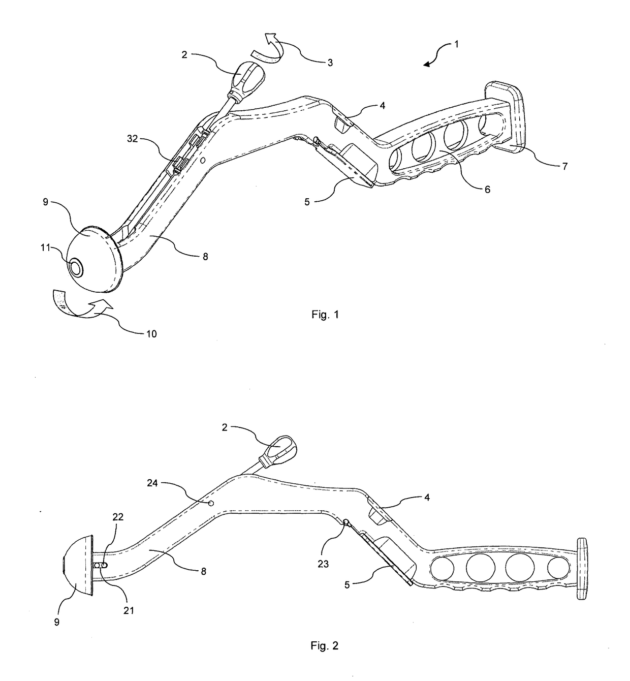
Figure 2 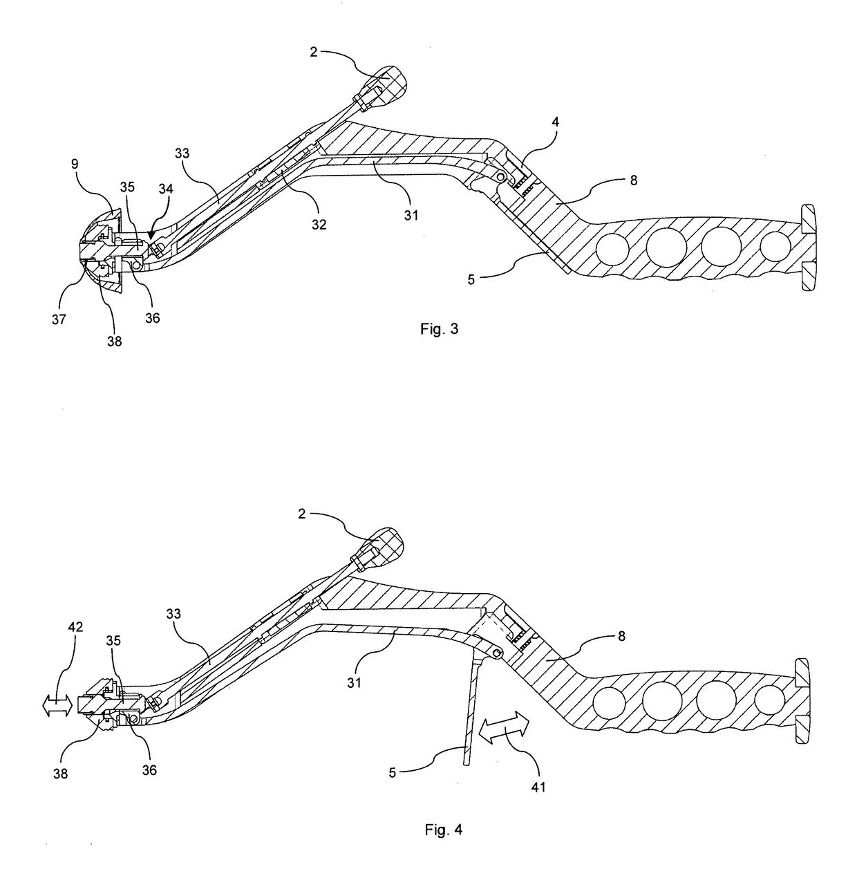
Figure 3
Abstract
Description
CROSS REFERENCE TO RELATED APPLICATIONS
[0001] This application claims the benefit of U.S. Provisional Application No. 62 / 062,166, filed Oct. 10, 2014, entitled: “ACETABULAR CUP IMPACTOR”, the contents of which are incorporated herein by reference thereto.COPYRIGHT & LEGAL NOTICE
[0002] A portion of the disclosure of this patent document contains material which is subject to copyright protection. The Applicant has no objection to the facsimile reproduction by anyone of the patent document or the patent disclosure as it appears in the Patent and Trademark Office patent file or records, but otherwise reserves all copyright rights whatsoever. Further, no references to third party patents or articles made herein is to be construed as an admission that the present invention is not entitled to antedate such material by virtue of prior invention.FIELD OF THE INVENTION
[0003] This invention relates to a surgical cup impactor, method, kit, surgical system and surgical apparatus for use in insertin...
Examples
second embodiment
[0043]Referring now to FIG. 9A, in a second embodiment, a clamping slide 91 having a concave kidney bean shape is shown. Movement of the clamping lever 31 induced rotation of the clamping slide 91 around the pivoting pin 93. The retaining section 92 of distal drive train shaft 94, which slides on the concave face of the clamping slide 91, follows the movement of the clamping slide and is pulled backward. As described above, the backward displacement of the distal drive train shaft 94 locks the acetabular cup prosthesis against the impactor nose.
third embodiment
[0044]Referring now to FIG. 9B, in a third embodiment, a clamping slide 95 is shown having a convex kidney bean shape. Movement of the clamping lever 31 induced rotation of the clamping slide 95 around the pivoting pin 97. The spherical retaining section 96 of distal drive train shaft 98, which slides on the convex face of the clamping slide 95, follows the movement of the clamping slide and is pulled backward. As described above, the backward displacement of the distal drive train shaft 98 locks the acetabular cup prosthesis against the impactor nose.
[0045]Referring now to FIGS. 10, 11 and 12 a variant of the embodiment of FIGS. 2, 3 and 4 is shown in which the clamping handle 5′ of the cup impactor l′ is located on the top of the impactor body 8′. Pulling on the clamping handle 5′ releases the cup 9 (by moving the threaded tip 37 forward), and pushing on the clamping handle 5′ locks the cup 9 (by moving the threaded tip 37 backward).
[0046]Referring now to FIGS. 13 and 14, differen...