
Method for controlling a piezoelectric actuator which is used to displace an element
Patent Information
- Authority / Receiving Office
- US · United States
- Current Assignee / Owner
- Publication Date
- 2005-04-26
- Estimated Expiration
- Not applicable · inactive patent
Smart Images
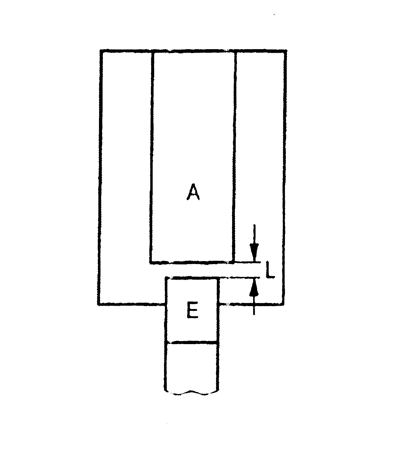
Figure 1 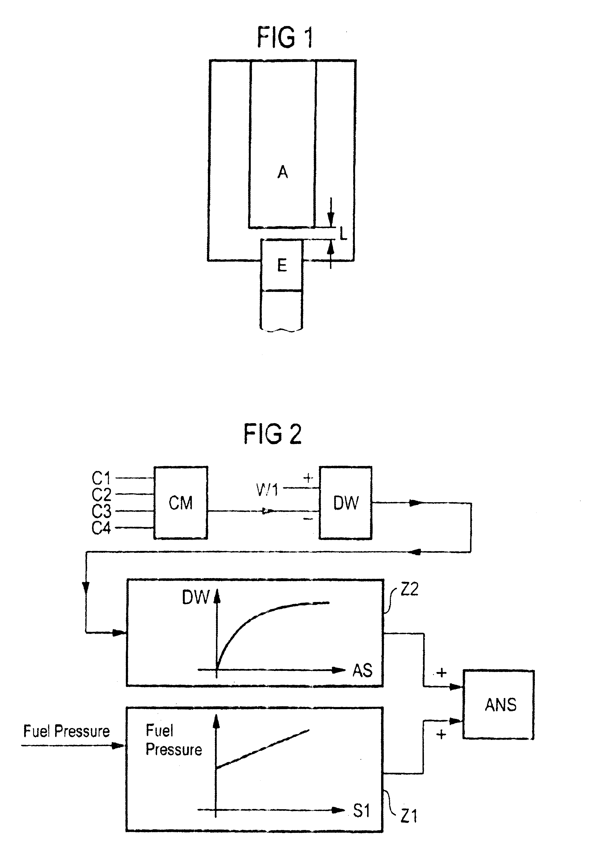
Figure 2
Abstract
Description
[0001] This is a U.S. national stage of application No. PCT / DE02 / 01596, filed on 02 May 2002. Priority is claimed on the following application(s): Country: Germany, Application No.: 101 23 372.8, Filed: 14 May 2001, under 35 U.S.C. §119(a) and 35 U.S.C. §365(b).BACKGROUND OF THE INVENTION
[0002] 1. Field of the Invention
[0003] The invention relates to a method for controlling a piezoelectric actuator which is used to displace an element. With a method of this kind the actuator has a control voltage applied to it. Because of the change in length of the actuator induced by the activation the element is displaced.
[0004] 2. Description of the Prior Art
[0005] Piezoelectric actuators are used for example in fuel injection systems. In this case the element is a control valve which is operated by the actuator.
[0006] Since the length of the piezoelectric actuator is dependent on temperature, a safety gap, referred to as the return stroke, should exist between the actuator in the non-activated state...
Examples
Embodiment Construction
[0034]In the exemplary embodiment there are provided four fuel injectors which feed a combustion chamber. Each of the fuel injectors has a piezoelectric actuator A which is used to displace an element E which is implemented as a control valve. Provided between the actuators A in the non-activated state and the elements E there is in each case a gap which is referred to as return stroke L (see FIG. 1).
[0035]An electronic control unit (ECU) which controls the actuators is provided. In the ECU, there is stored in a characteristics map a first assignment Z1 between fuel pressure and a first energy and hence a first voltage S1. The first assignment Z1 specifies the control energies and hence the control voltages ANS that are required in each case at operating temperature and at specific fuel pressures in order to achieve an optimal amount of fuel to be injected. Furthermore there is stored in a further characteristics map a second assignment Z2 of difference values DW to compensation ene...