
Swing type switching device including magnet and magnetoresistive element
Patent Information
- Authority / Receiving Office
- US · United States
- Current Assignee / Owner
- Publication Date
- 2009-08-06
- Estimated Expiration
- Not applicable · inactive patent
Smart Images
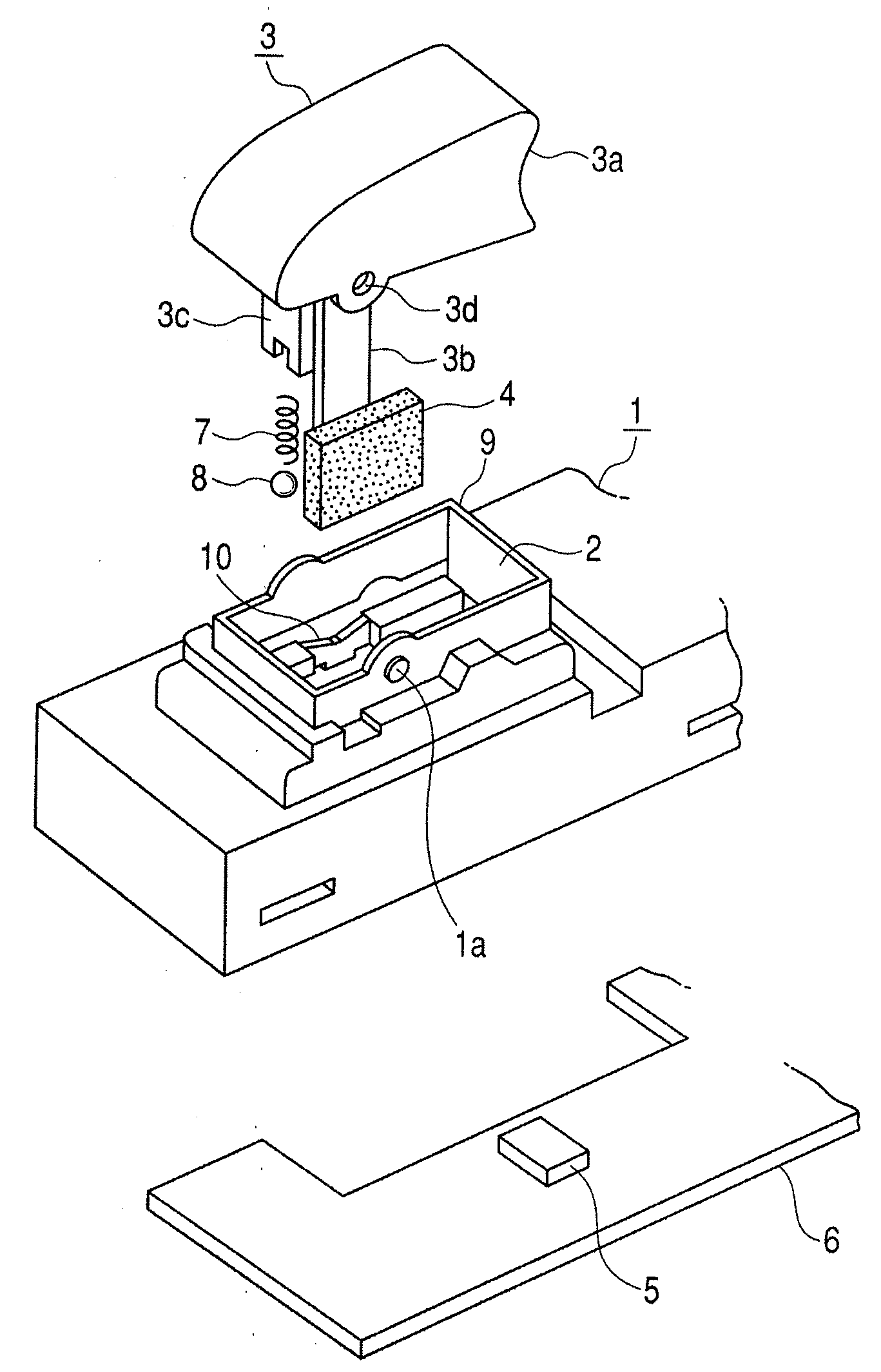
Figure 1 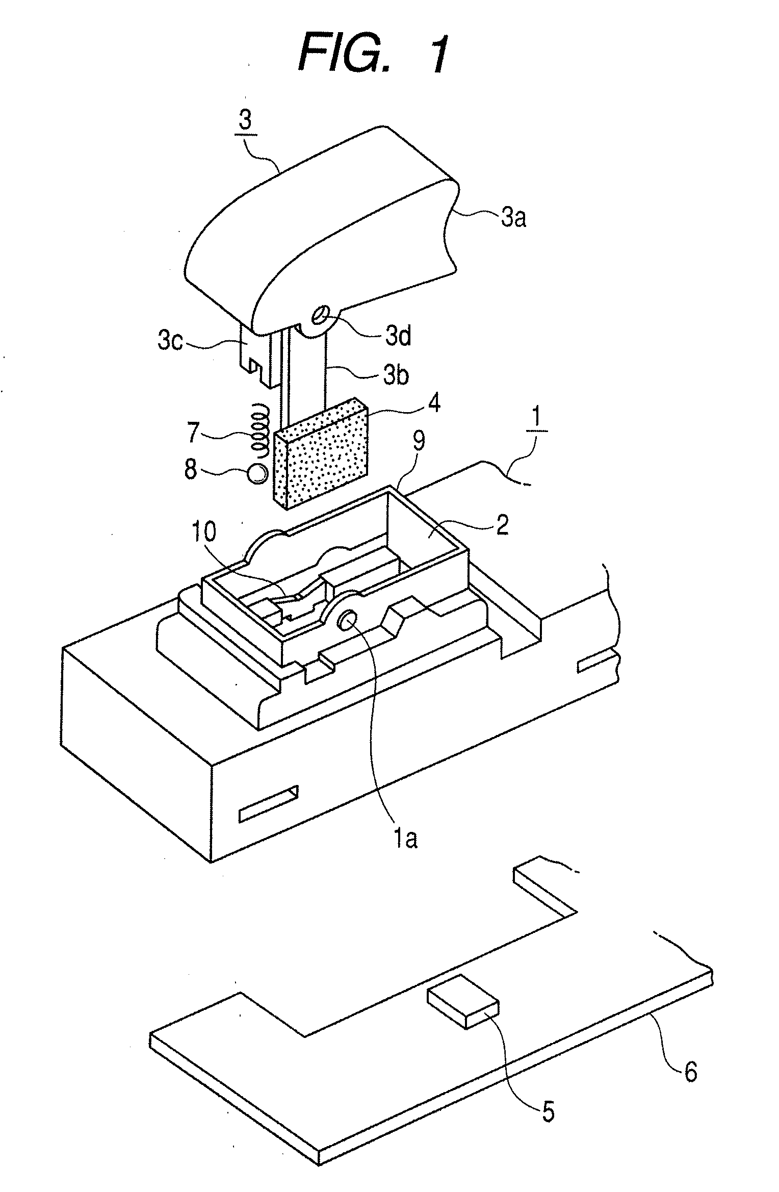
Figure 2 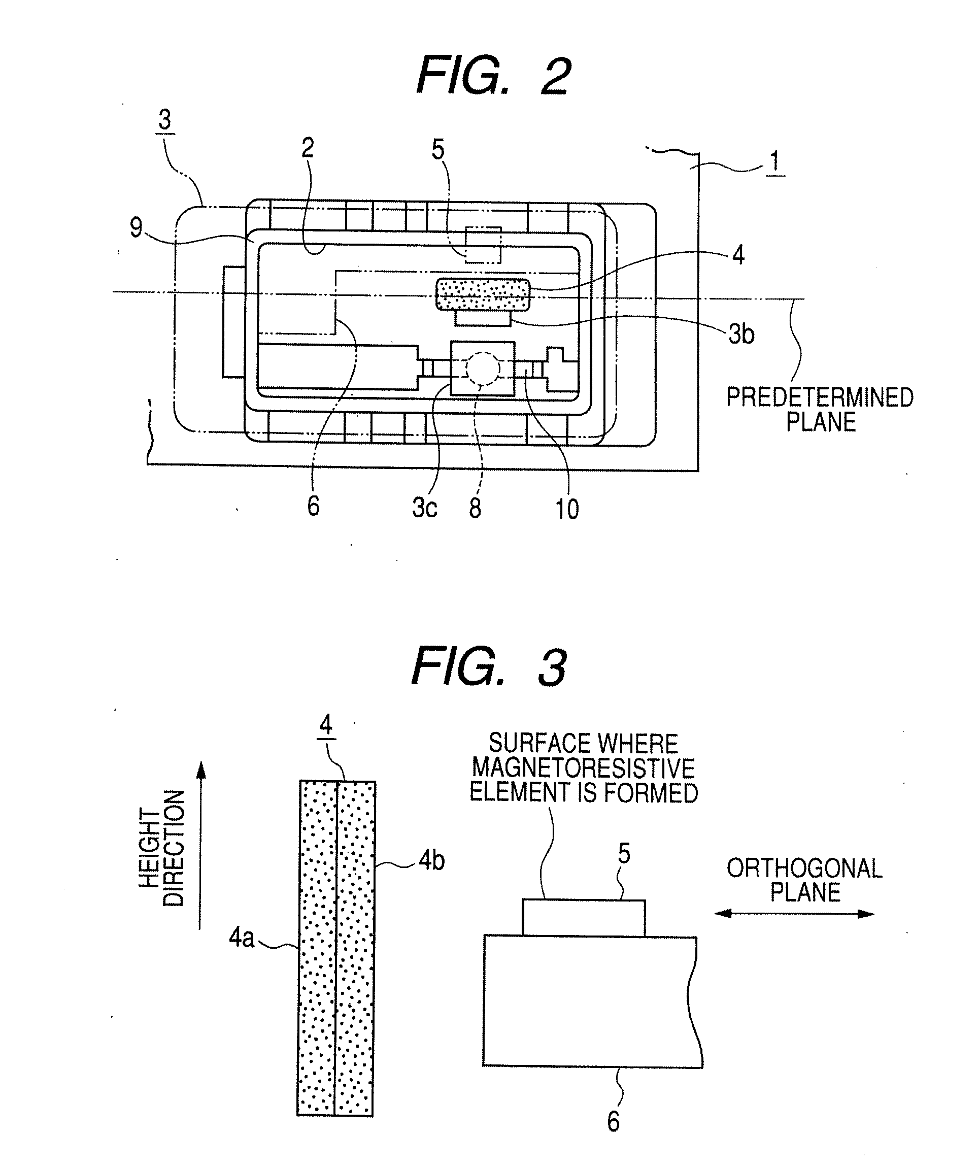
Figure 3
Abstract
Description
CROSS REFERENCE TO RELATED APPLICATION
[0001] The present invention contains subject matter related to and claims priority to Japanese Patent Application No. 2008-024043 filed in the Japanese Patent Office on Feb. 4, 2008, the entire contents of which being incorporated herein by reference.BACKGROUND
[0002] 1. Field of the Disclosure
[0003] The present disclosure relates to a swing type switching device for performing a switching operation by the swing of an operation body, such as a switching device for a power window of a vehicle, and particularly to, a swing type switching device that uses a magnetism detecting method.
[0004] 2. Description of the Related Art
[0005] Generally, a swing type switching device such as a switching device for a power window has a structure in which, if an operation body swings, a movable contact and a fixed contact come into contact with or separate from each other to perform the switching. However, the swing type switching device of this type has a disadvantag...
Examples
Embodiment Construction
[0019]Embodiments of the invention will be described with reference to drawings. FIG. 1 is an exploded perspective view of a swing type switching device according to an embodiment of the invention. FIG. 2 is an explanatory diagram showing the inner structure of the switching device. FIG. 3 is an explanatory diagram showing a relative positional relationship between a permanent magnet and a GMR sensor of the embodiment. FIG. 4 is a characteristic diagram showing magnetic field vectors of the permanent magnet of the embodiment. FIG. 5 is an explanatory diagram showing a neutral position and a maximum displacement position of the permanent magnet of the embodiment. FIG. 6 is a circuit diagram of the GMR sensor of the embodiment. FIG. 7 is a characteristic diagram showing a relationship between the displacement of the permanent magnet and the output voltage of the GMR sensor of the embodiment.
[0020]A switching device shown in FIGS. 1 and 2 is a swing type switching device that uses a ma...