
System providing ventricular pacing and biventricular coordination
a biventricular coordination and ventricular pacing technology, applied in the field of cardiac rhythm management systems, can solve the problems of reducing blood circulation, drug therapy not always effective in treating certain patients' arrhythmias, and reducing blood circulation
Patent Information
- Authority / Receiving Office
- US · United States
- Patent Type
- Patents(United States)
- Current Assignee / Owner
- Publication Date
- 2008-12-02
- Estimated Expiration
- Not applicable · inactive patent
Smart Images
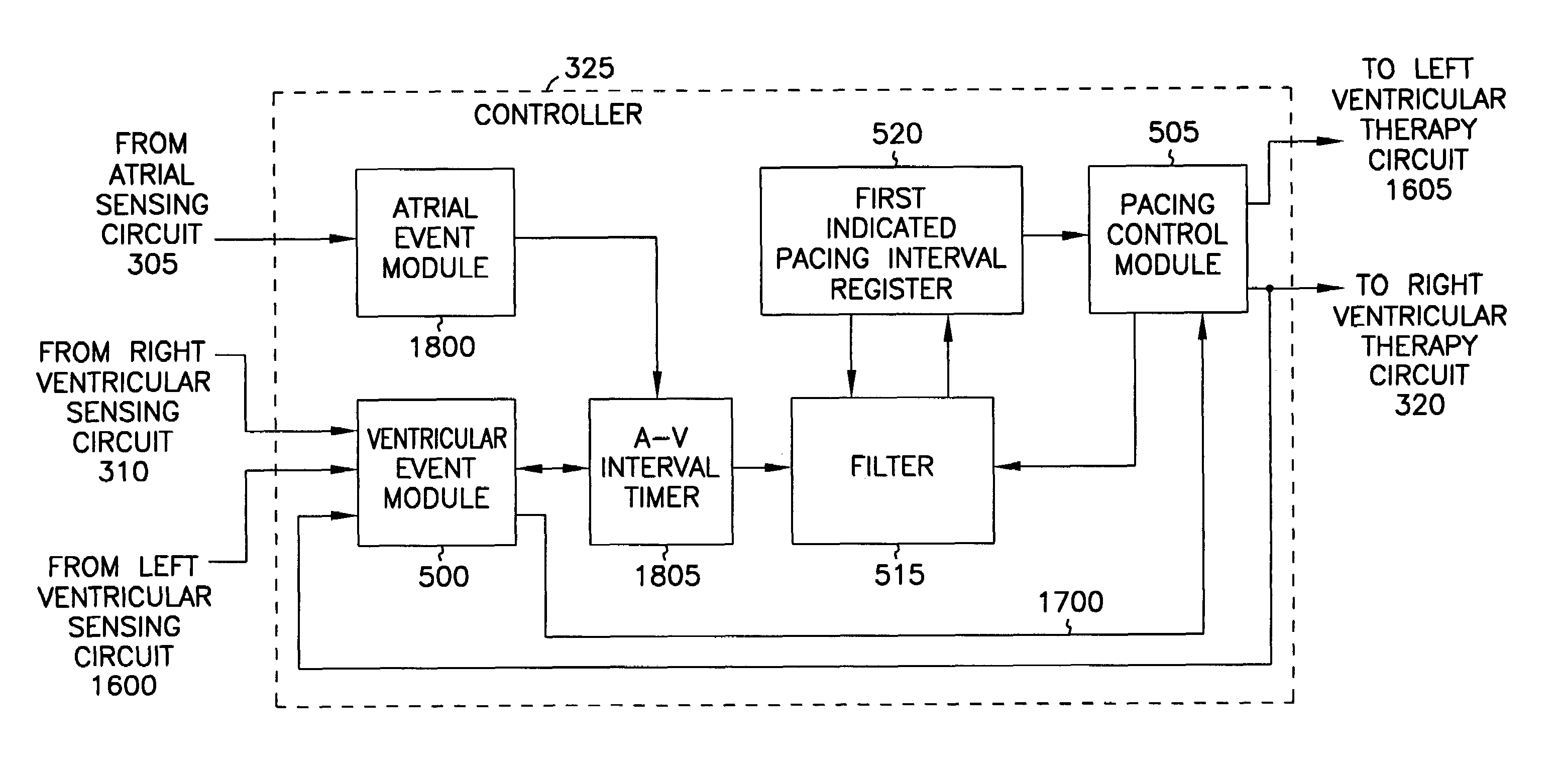
Figure 1 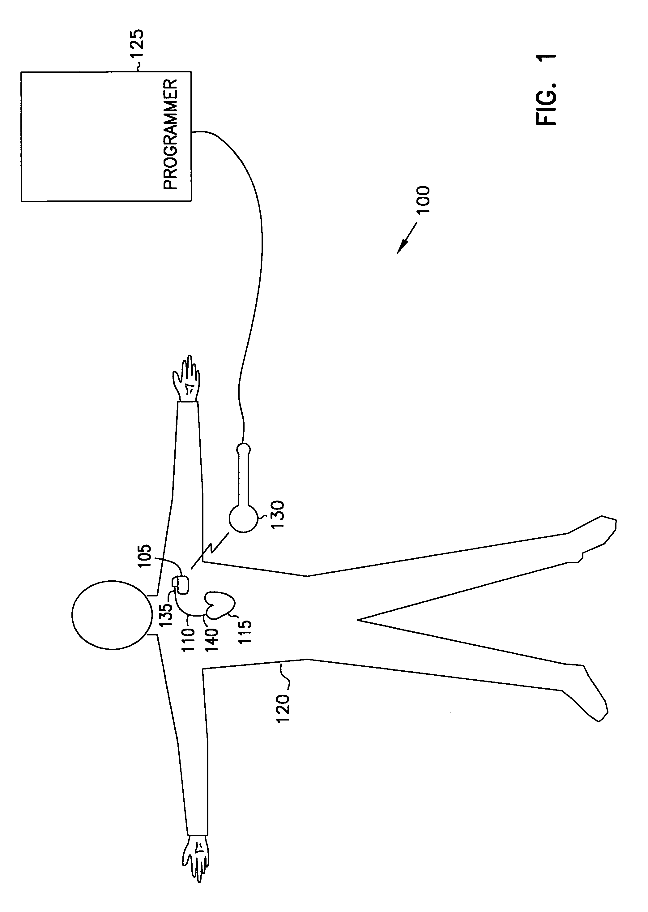
Figure 2 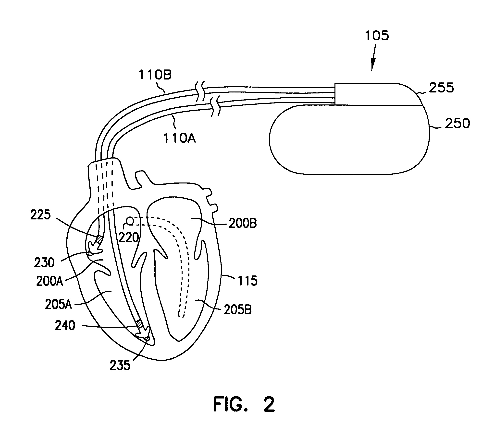
Figure 3
Abstract
Description
CROSS REFERENCE TO RELATED APPLICATIONS
[0001] This application is a continuation of U.S. patent application Ser. No. 09 / 316,515, filed on May 21, 1999 now U.S. Pat. No. 7,062,325, the specification of which is incorporated herein by reference in its entirety.
[0002] This application is related to the following, commonly assigned patent applications: “Cardiac Rhythm Management System Promoting Atrial Pacing,” U.S. Pat. No. 6,351,669; “Cardiac Rhythm Management System With Atrial Shock Timing Optimization,” U.S. Pat. No. 6,430,438; and “System Providing Ventricular Pacing and Biventricular Coordination,” U.S. Pat. No. 6,285,907; each of which were filed on May 21, 1999, each of which disclosure is herein incorporated by reference in its entirety.TECHNICAL FIELD
[0003] The present system relates generally to cardiac rhythm management systems and particularly, but not by way of limitation, to a method and apparatus for treating irregular ventricular contractions, such as during an atrial arr...
Examples
example 1
FILTER EXAMPLE 1
[0058]In general terms, for one embodiment, device 105 obtains V-V intervals between successive sensed or evoked ventricular beats. Device 105 computes a new first indicated pacing interval based at least in part on the duration of the most recent V-V interval and a previous value of the first indicated pacing interval. Device 105 provides pacing therapy delivered at a rate corresponding to the inverse of the duration of the first indicated pacing interval.
[0059]FIG. 6 is a signal flow diagram illustrating generally, by way of example, but not by way of limitation, one embodiment of operating filter 515. Upon the occurrence of a sensed or evoked ventricular beat, timer 510 provides filter 515 with the duration of the V-V interval concluded by that beat, which is referred to as the most recent V-V interval (VVn). Filter 515 also receives the previous value of the first indicated pacing interval (Tn-1) stored in register 520. The most recent V-V interval VVn and the pr...
example 3
FILTER EXAMPLE 3
[0067]In another embodiment, these coefficients can be more particularly described using an intrinsic coefficient (a), a paced coefficient (b), and a weighting coefficient (w). In one such embodiment, A=a·w, B=(1−w), C=b·w, and D=(1−w). In one example, operation of the filter 515 is described by Tn=a·w·VVn+(1−w)·Tn-1, if VVn is concluded by an intrinsic beat, otherwise is described by Tn=b·w·VVn+(1−w)·Tn-1, if VVn is concluded by a paced beat, as illustrated generally, by way of example, but not by way of limitation, in the signal flow graph of FIG. 8. If no ventricular beat is sensed during the new first indicated pacing interval Tn, which is measured as the time from the occurrence of the ventricular beat concluding the most recent V-V interval VVn, then pacing control module 505 instructs ventricular therapy circuit 320 to deliver a ventricular pacing pulse upon the expiration of the new first indicated pacing interval Tn. In one embodiment, the coefficients a and...
example 2
CONTROLLER EXAMPLE 2
[0077]FIG. 10 is a schematic diagram illustrating generally, by way of example, but not by way of limitation, another conceptualization of portions of controller 325, with certain differences from FIG. 9 more particularly described below. In FIG. 10, controller 325 includes an atrial tachyarrhythmia (AT) detection module 1000 that receives a signal from atrial sensing circuit 305. The received signal includes information about atrial events, from which AT detection module 1000 determines the presence or absence of one or more atrial tachyarrhythmias, such as atrial fibrillation.
[0078]In one embodiment, AT detection module 1000 provides a control signal, to pacing control module 505, that indicates the presence or absence of an atrial tachyarrhythmia, such as atrial fibrillation. In one embodiment, selection module 915 selects between the first and second indicated pacing intervals as illustrated, by way of example, but not by way of limitation, in Table 1.
[0079]
T...