
Measuring technology and computer numerical control technology
a technology applied in the field of measuring technology and computer numerical control technology, can solve the problems of measurement error, reducing efficiency, and reducing the time required for measuremen
Patent Information
- Authority / Receiving Office
- US · United States
- Patent Type
- Patents(United States)
- Current Assignee / Owner
- Publication Date
- 2009-03-10
Smart Images
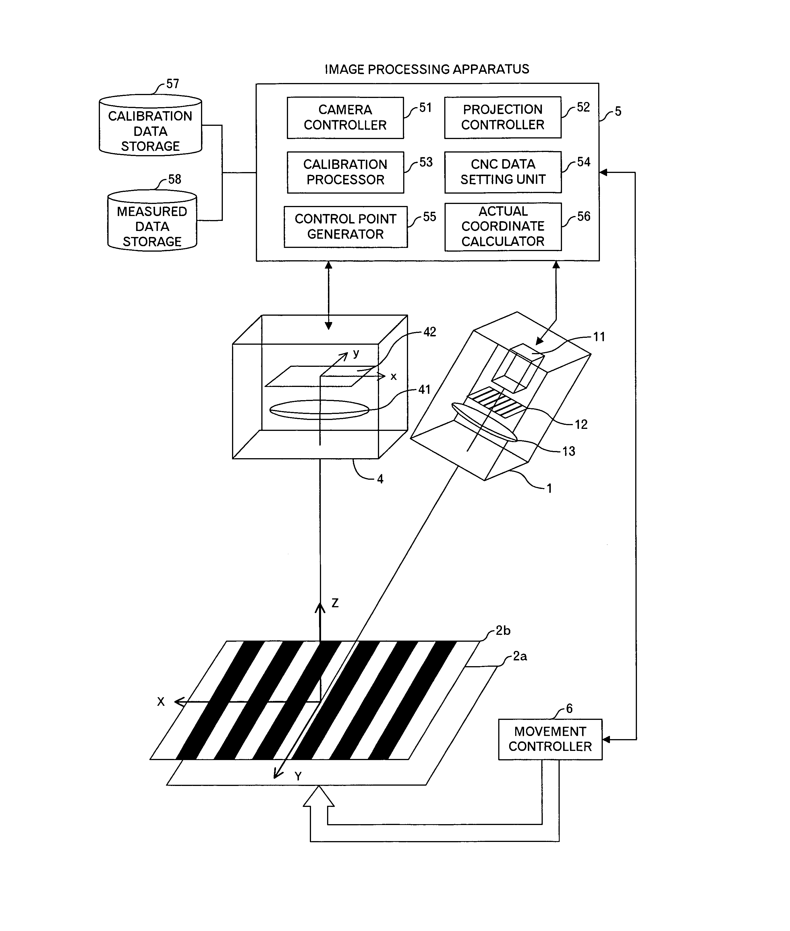
Figure 1 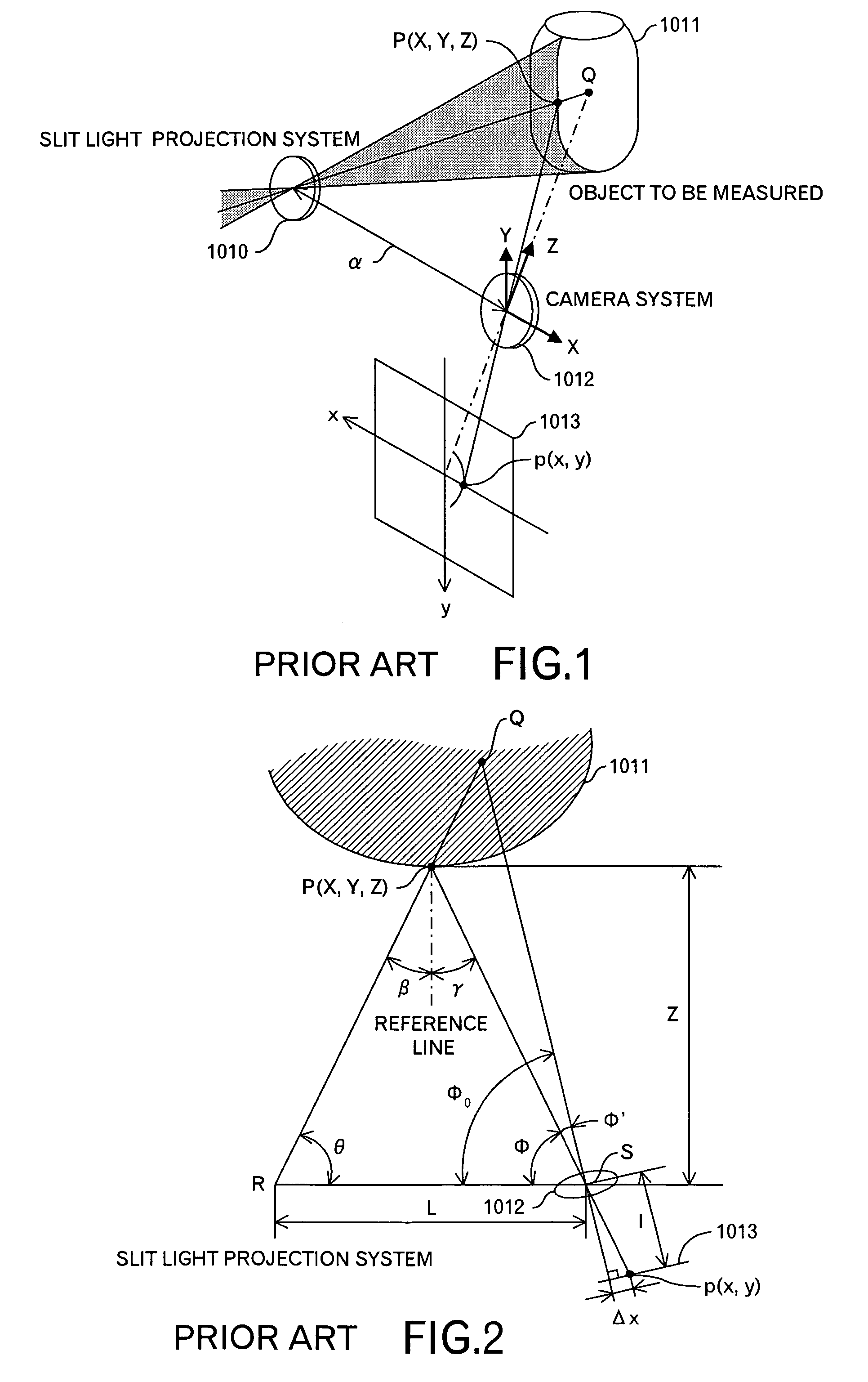
Figure 2 
Figure 3
Abstract
Description
TECHNICAL FIELD OF THE INVENTION
[0001] The present invention relates to a technique to measure the three-dimensional shape of an object to be measured by projecting light to the object to be measured.BACKGROUND OF THE INVENTION
[0002] The measurement of a three-dimensional shape has been used not only in an industrial field but also in social various fields such as medicine, biology, archaeology, and the examination and restoration of works of art. In the three-dimensional measurement, non-contact type optical measurement has been more desired than conventional contact type measurement. Region measurement in the optical measurement is broadly divided into a light section method of measuring a region by scanning the region with one linear slit light in a direction perpendicular to a direction of slit and a measurement method of measuring a region by a surface.
[0003] As for the light section method, although various modes have been developed, it is basically based on a principle shown in ...
Examples
first embodiment
[0090]FIG. 4 shows a functional block diagram in the first embodiment of the present invention using a fringe pattern projection method. A CNC apparatus (for example, a machine tool, but it is not intended to limit the CNC apparatus to the machine tool) including a measuring apparatus in this embodiment has: an image processing apparatus 5 that performs a main processing in this embodiment and is a computer; a liquid crystal projector 1 that is connected to the image processing apparatus 5 and has a projection unit 11 such as a lamp, a liquid crystal panel 12 forming a grating, and a lens 13; a camera 4 that is connected to the image processing apparatus 5 and has a lens 41, a CCD 42, and a memory (not shown); a reference plane 2 that is a reference plane at the time of calibration (however, it is assumed that a reference plane for height Z=Z1 is indicated as the reference plane 2a and that a reference plane for height Z=Z2 is indicated as the reference plane 2b); and a movement con...
second embodiment
[0165]Next, the configuration in a case of using the light section method will be described with reference to FIGS. 23 to 29. First, FIG. 23 shows a functional block diagram. A CNC apparatus including a measuring unit in this embodiment includes a image processing apparatus 2305 that performs a main processing in this embodiment and is a computer, a measurement unit 2330 having a projection unit 2301 that is connected to the image processing apparatus 2305 and projects slit light and a camera 2304, a reference plane 2302 that is used as a reference plane (where, it is assumed that a reference plane for height Z=Z1 is denoted by 2302a and that a reference plane for Z=Z2 is denoted by 2302b) at the time of calibration, and a movement controller 2306 that is connected to the image processing apparatus 2305 and controls movement at least in a Z direction of the reference plane 2302. The projection unit 2301 has a light source 2311 such as laser light source and a slit 2312. Further, the...