
Side airbag apparatus, motor vehicle seat, and gas distributor of inflator
Patent Information
- Authority / Receiving Office
- US · United States
- Current Assignee / Owner
- Publication Date
- 2009-10-06
Smart Images
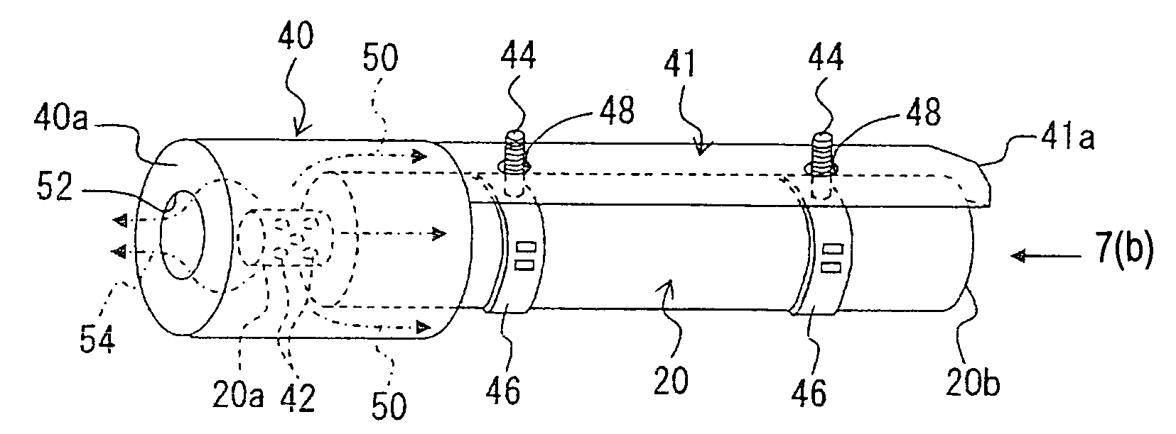
Figure 1 
Figure 2 
Figure 3
Abstract
Description
BACKGROUND OF THE INVENTION AND RELATED ART STATEMENT
[0001] The present invention relates to a side airbag apparatus for restraining an occupant in the event of a side collision or the like in a motor vehicle such as an automobile or the like, and more particularly, to a side airbag apparatus including a side airbag inside of which is partitioned into a plurality of chambers, a motor vehicle seat including the same, and a gas distributor of an inflator.
[0002] A side airbag apparatus is known for restraining an occupant's body by inflating a side airbag toward a side portion of the occupant by means of an inflator in the event a side collision, a rollover or the like of a motor vehicle such as an automobile. The side airbag apparatus is housed in, for example, a seat back portion of a seat. The side airbag is inflated and deployed into a space between the occupant and a side wall portion of the vehicle body from the seat back portion by means of the gas blown out of the inflator in the...
Examples
second embodiment
[0081]Hereinbelow, the present invention will be explained with reference to the drawings. In this embodiment, clips 46 for supporting the inflator 20 are arranged in two positions, and a hooking portion 41a as a stopper is provided in a tongue piece portion 41 at an end portion of the other side in the cylinder axis direction thereof.
[0082]FIGS. 7(a) and 7(b) are views illustrating an entire structure of the sleeve 40. FIG. 7(a) is a perspective view thereof, and FIG. 7(b) is a view looking from a direction of an arrow 7(b) in FIG. 7(a).
first embodiment
[0083]In FIGS. 7(a) and 7(b), different from the first embodiment, a hole 48 is provided in two positions in the tongue piece portion 41 of the sleeve 40, respectively, i.e. at one side (left side in FIG. 7(a)) and the other side (right side in FIG. 7(a)) in a cylinder axis direction thereof, for passing the bolts 44 of the clips 46, which are provided in the two positions of the inflator in the axial direction thereof. By the bolts 44 passing through the holes 48, the sleeve 40 is engaged with the inflator 20 in a condition of covering one side (left side in FIG. 7(a), i.e., second chamber 28B side) of the inflator 20.
[0084]Further, the tongue piece portion 41 includes the hooking portion 41a at the end portion of the other side in the cylinder axis direction. The hooking portion 41a is, as shown in FIG. 7(b), provided to face the end portion 20b of the other side of the inflator 20 (being slightly spaced apart) in a manner so as to cover part of the end portion 20b, and is configu...