
Electromechanical locking device for a brake piston
a technology of electronic locking and brake piston, which is applied in the direction of braking systems, friction linings, transportation and packaging, etc., can solve the problems of not satisfying the response performance of such a wheel brake, the hydraulic pressure fluid does not behave ideally incompressibly, and the remaining space inside the brake piston is relatively large, so as to prevent mechanical warping and less hydraulic elasticity , the effect of easy reversibility
Patent Information
- Authority / Receiving Office
- US · United States
- Patent Type
- Patents(United States)
- Current Assignee / Owner
- Publication Date
- 2011-11-22
- Estimated Expiration
- Not applicable · inactive patent
Smart Images
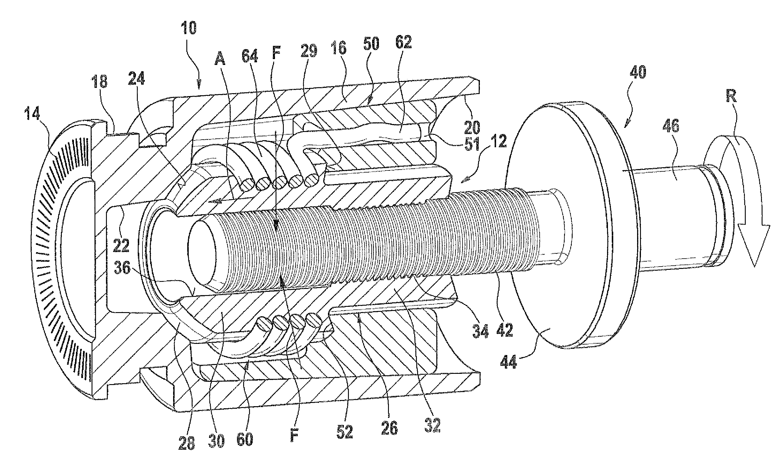
Figure 1 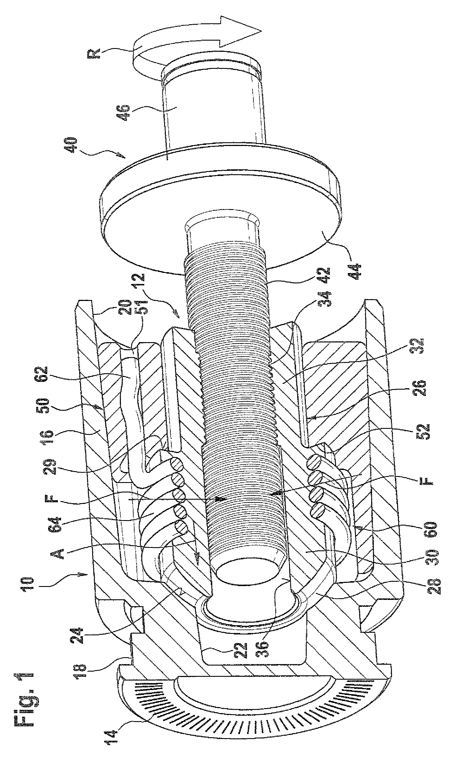
Figure 2 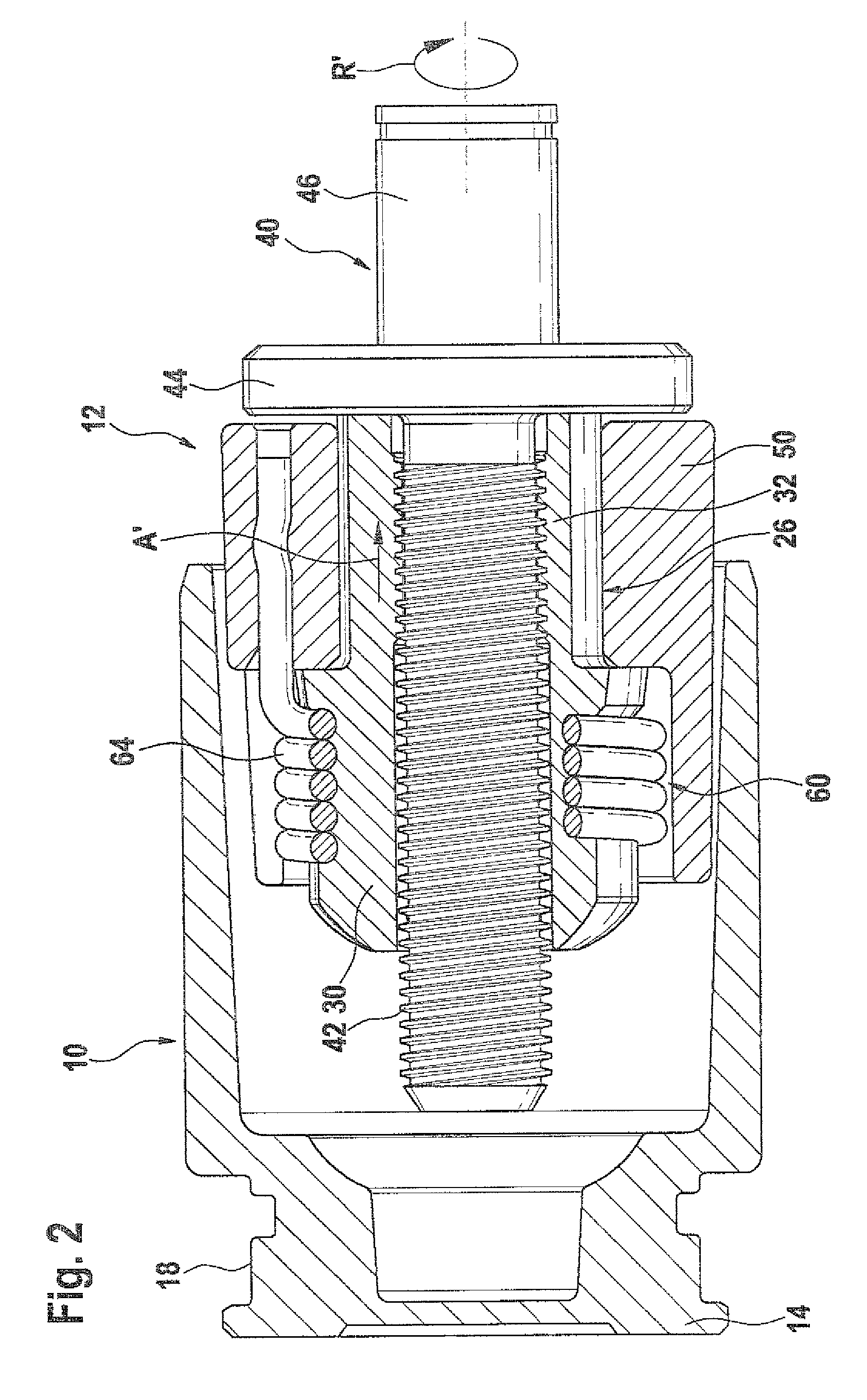
Figure 3
Abstract
Description
CROSS-REFERENCE TO RELATED APPLICATIONS
[0001] This application is based on German Patent Application No. 10 2007 053 278.6 filed on Nov. 8, 2007, upon which priority is claimed.BACKGROUND OF THE INVENTION
[0002] 1. Field of the Invention
[0003] The invention is based on an electromechanical locking device for a brake piston of a hydraulically actuated wheel brake.
[0004] 2. Description of the Prior Art
[0005] One such electromechanical locking device is know for instance from German Patent Disclosure DE 10 2005 055 084 A1. The wheel brake disclosed in this reference is hydraulically actuatable. The wheel brake has a hollow-cylindrical brake piston, whose interior is filled with hydraulic pressure fluid. In the event of brake actuation, a hydraulic pressure is built up by the driver of a vehicle. A pressure force causes a displacement of the brake piston relative to a brake cylinder, in which this brake piston is movably guided. The brake piston presses a brake lining against a rotating brake...
Examples
Embodiment Construction
[0018]In FIG. 1, a brake piston 10 is shown, with a locking device 12 built into it. The brake piston 10 is a hollow-cylindrical component, which is closed in pressure-fluid-tight fashion on one of its ends by a lining contact plate 14. The lining contact plate 14 and a piston shaft 16 are embodied in one piece with one another, and on the circumference of the brake piston 10, between the lining contact plate 14 and the piston shaft 16, a recess 18 is provided, which has a single perpendicular graduation from the outside inward. The interior of the brake piston 10 is divided into two portions 20, 22 of different inside diameters. A first portion 20, located at the open end of the brake piston 10, has a larger inside diameter than a second portion 22, which is oriented toward the lining contact plate 14 and is connected to the first portion 20. The transition from the first portion 20 to the second portion 22 is embodied as a conical indentation 24. This conical indentation is locate...