
Method and system for distributing work batches to processing units based on a number of enabled streaming multiprocessors
a multiprocessor and work batch technology, applied in the field of computer hardware, can solve the problems of reducing the processing throughput of the computer system, the work distribution and the processing unit b>12 may not have all the equivalent processing capabilities
Patent Information
- Authority / Receiving Office
- US · United States
- Patent Type
- Patents(United States)
- Current Assignee / Owner
- Publication Date
- 2017-03-14
Smart Images
Figure 1 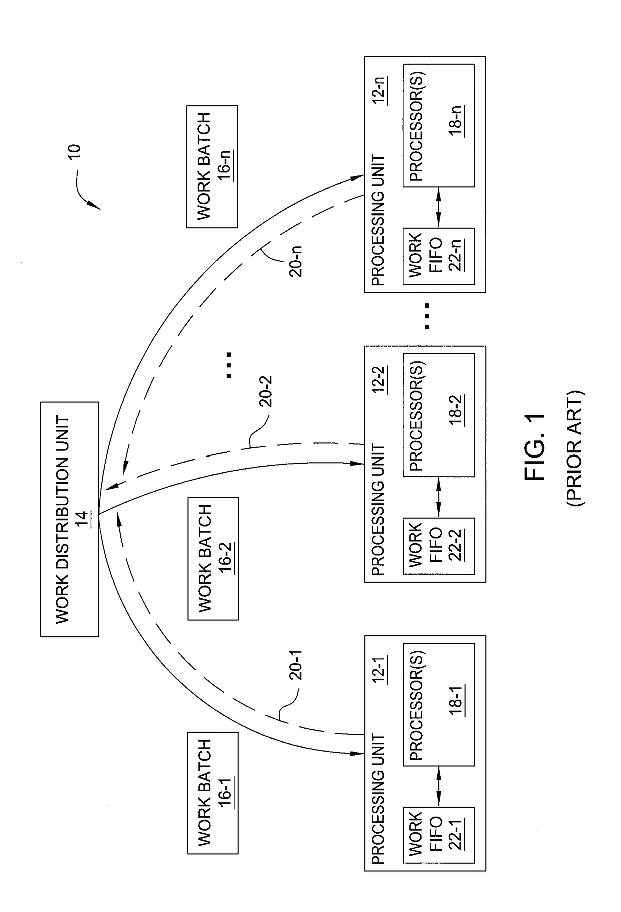
Figure 2 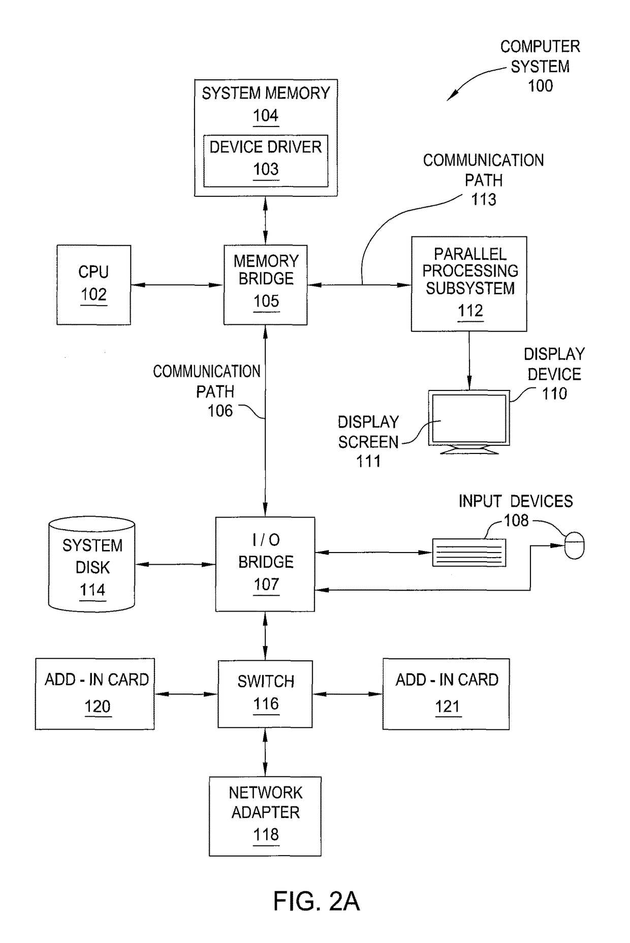
Figure 3
Abstract
Description
BACKGROUND OF THE INVENTION
[0001] Field of the Invention
[0002] The present invention generally relates to computer hardware and more specifically to a method and system for distributing work batches to processing units.
[0003] Description of the Related Art
[0004] A modern computer system may include one or more processing units that operate in parallel to perform a variety of processing tasks. FIG. 1 illustrates one such computer system. As shown, computer system 10 includes processing units 12-1, 12-2, and 12-n. A work distribution unit 14 is coupled to each of the processing units 12 and distributes work batches 16-1, 16-2, and 16-n to processing units 12-1, 12-2, and 12-n, respectively. As referred to herein, a “work batch” includes a set of processing tasks to be performed by a particular processing unit 12. Work distribution unit 14 distributes work batch 16-1 to processing unit 12-1, work batch 16-2 to processing unit 12-2, and work batch 16-n to processing unit 12-n. Processing un...
Examples
Embodiment Construction
[0027]In the following description, numerous specific details are set forth to provide a more thorough understanding of the invention. However, it will be apparent to one of skill in the art that the invention may be practiced without one or more of these specific details. In other instances, well-known features have not been described in order to avoid obscuring the invention.
System Overview
[0028]FIG. 2A is a block diagram illustrating a computer system 100 configured to implement one or more aspects of the invention. Computer system 100 includes a central processing unit (CPU) 102 and a system memory 104 communicating via an interconnection path that may include a memory bridge 105. Memory bridge 105, which may be, e.g., a Northbridge chip, is connected via a bus or other communication path 106 (e.g., a HyperTransport link) to an I / O (input / output) bridge 107. I / O bridge 107, which may be, e.g., a Southbridge chip, receives user input from one or more user input devices 108 (e.g.,...