

Contact carrier
a contact carrier and carrier technology, applied in the direction of coupling device connection, coupling contact member, securing/insulating coupling, etc., can solve the problems of only possible fault-free contact, not always guaranteed, and minimum accuracy is necessary, so as to minimize the risk of contact carriers resting one on top of the other, and eliminate or at least minimize disadvantages
Patent Information
- Authority / Receiving Office
- US · United States
- Patent Type
- Patents(United States)
- Current Assignee / Owner
- Publication Date
- 2018-05-08
Smart Images
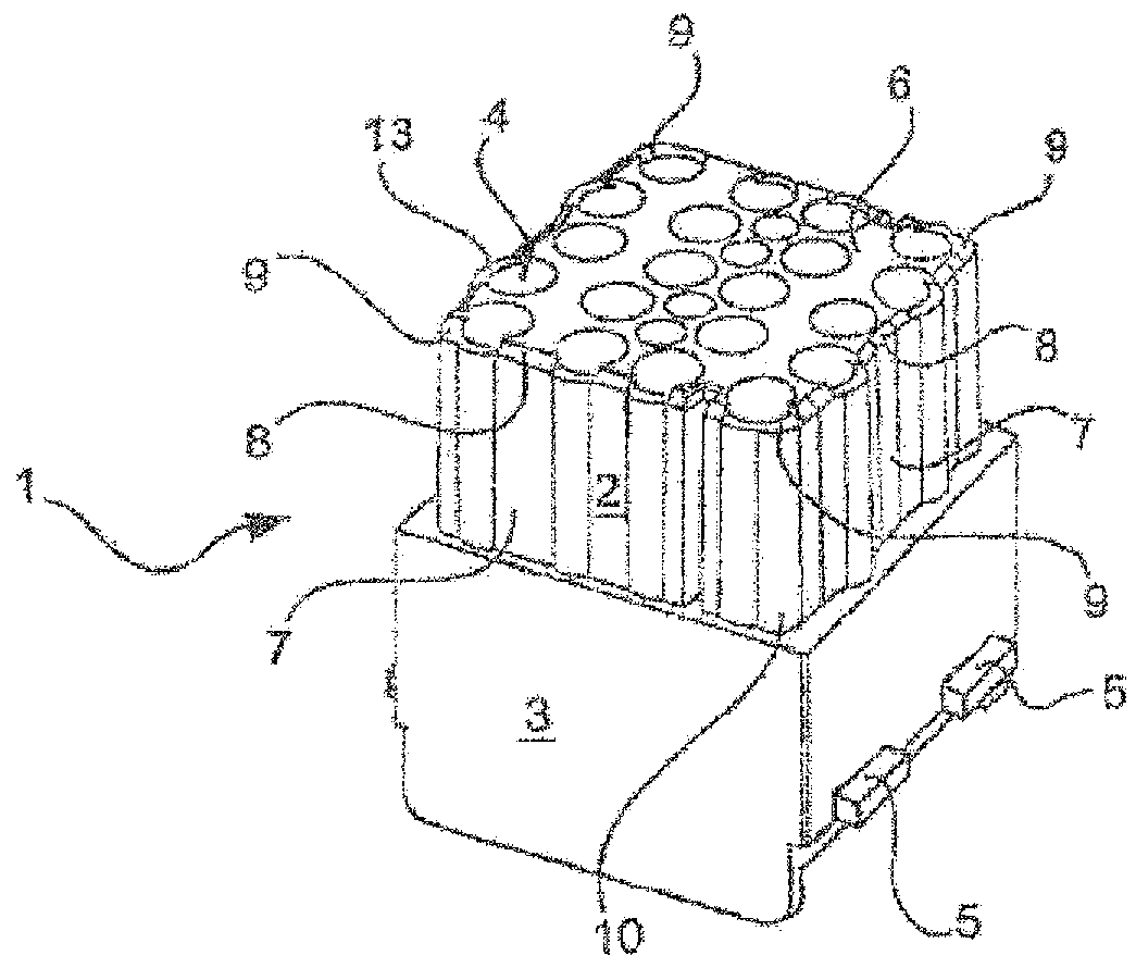
Figure 1 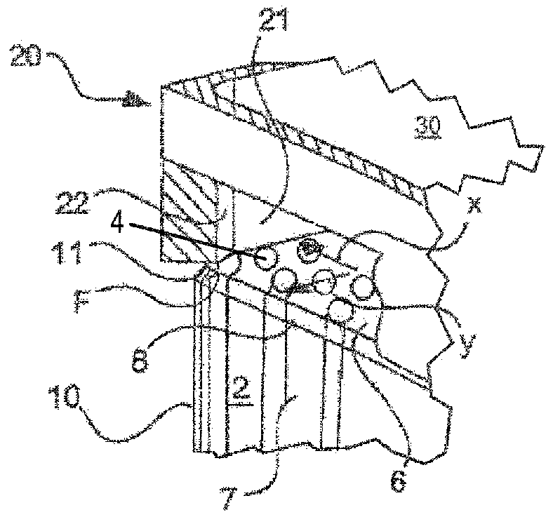
Figure 2 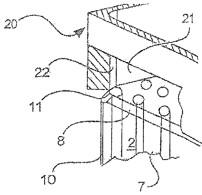
Figure 3
Abstract
Description
CROSS REFERENCE TO RELATED APPLICATIONS
[0001] Not applicable.STATEMENT REGARDING FEDERALLY SPONSORED RESEARCH OR DEVELOPMENT
[0002] Not applicable.BACKGROUND OF THE INVENTION
[0003] The invention relates to a contact carriers.
[0004] Contact carriers are required in connection technology in order to receive contacts, preferably in plug connectors. Here, the contact carrier serves to receive contact elements such as electric, pneumatic or optical contacts.
[0005] The contact carrier has cavities, in which the contact elements are received and secured. The cavities are usually formed here as bores, which penetrate the contact carrier completely. On a side of the contact carrier referred to as the connection side, a conductor can thus be conductively connected to the contact element received in the cavity.
[0006] On the side opposite the connection side, referred to as the plugging side, the contact element received in the cavity is provided with a second contact carrier for contacting. The secon...
Examples
Embodiment Construction
[0040]The figures contain schematic illustrations simplified in part. Identical reference signs are sometimes used for elements that are similar, but possibly not identical. Different views of the same elements could be scaled differently.
[0041]FIG. 1 shows a contact carrier 1 from a perspective view. The contact carrier 1 has two regions, wherein the region illustrated here at the bottom forms a retaining region 3 and the region illustrated here at the top forms a plugging region 2.
[0042]A multiplicity of cavities 4 are formed in the contact carrier 1. Here, the cavities 4 extend from a cover face 6 terminating the plugging region 2 through the entire plugging region 2 and the entire retaining region 3. The cavities 4 exit from the retaining region 3 of the contact carrier 1—and also from the plugging region 2—on the terminating face of the retaining region 3 (said face not being visible here).
[0043]The cavities 4 are intended to receive contact elements. Here, contact elements are...