Ventilator

A technology of ventilation device and external air, which is applied to airflow control elements, household heating, lighting and heating equipment, etc. Effects of wind efficiency, improved heat exchange efficiency, and prevention of flow resistance and flow loss

Inactive Publication Date: 2008-11-19
LG ELECTRONICS (TIANJIN) APPLIANCES CO LTD
View PDF6 Cites 0 Cited by
  • Summary
  • Abstract
  • Description
  • Claims
  • Application Information

AI Technical Summary

Problems solved by technology

[0005] But according to the ventilation device of the prior art, the outdoor air or indoor air passing through the heat exchanger 8 directly passes through the suction fan or the exhaust fan 20, so that the air is set at the partial flow speed of the suction fan 10 or the exhaust fan 20. Sudden acceleration leads to turbulent flow, resulting in flow resistance and flow loss, thereby reducing air supply efficiency
In addition, according to the ventilation device of the prior art, the suction fan 10 or the exhaust fan 20 are due to being arranged at the central part of the heat exchanger 8, and the air flows uniformly in front of the heat exchanger 8, while the A large pressure difference is generated between one side and the other side at a position close to the suction fan 10 or exhaust fan 20, and a small pressure difference is generated at a position far from the suction fan 10 or exhaust fan 20 , so that a high-speed air flow is formed near the suction fan 10 or the exhaust fan 20 in the heat exchanger 8, so that most of the air is only in the heat exchanger 8 near the suction fan 10 or the exhaust fan 20 Heat exchange occurs on the surface, thereby reducing the heat exchange efficiency

Method used


Image

  • Ventilator
  • Ventilator
  • Ventilator

Examples


Embodiment Construction

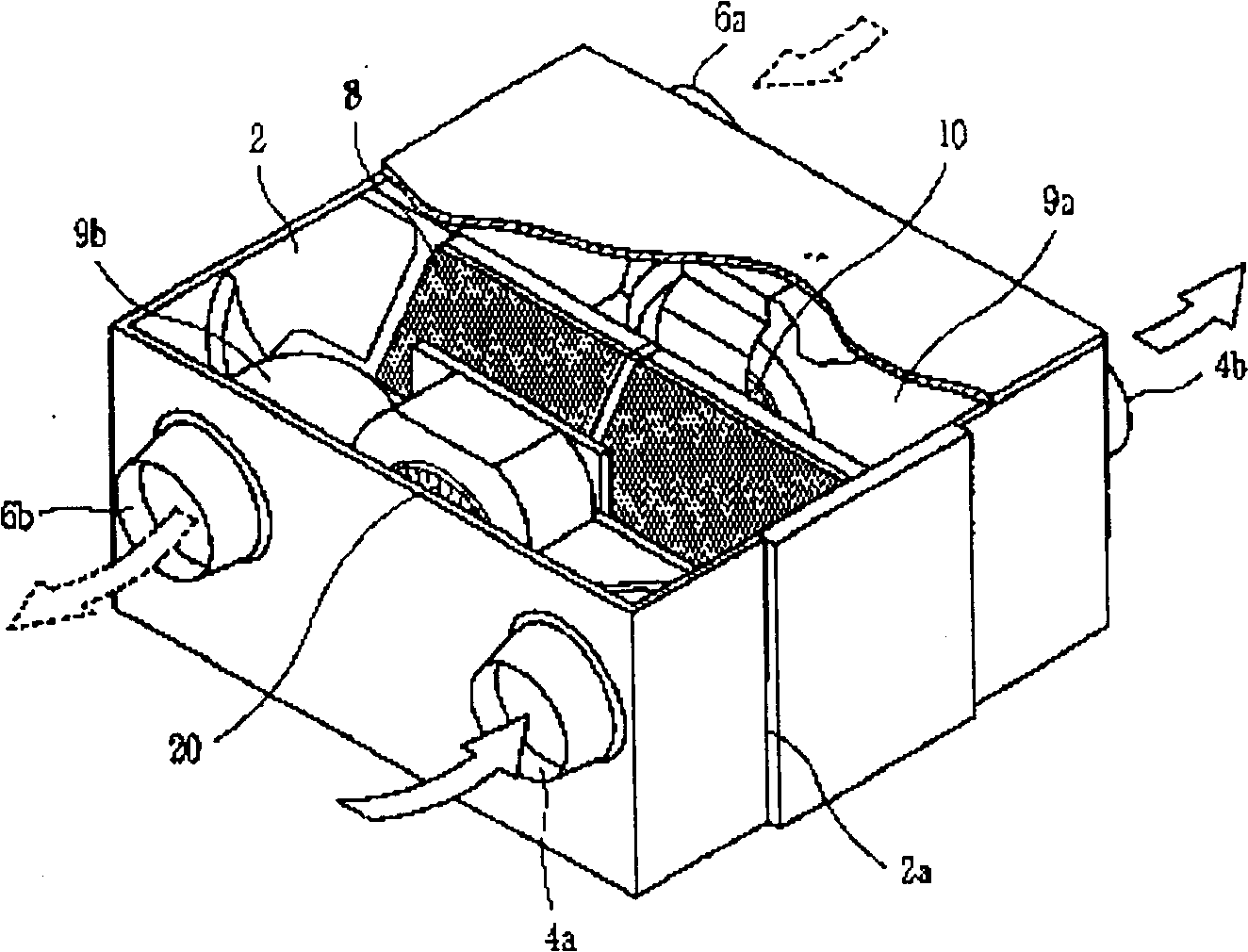
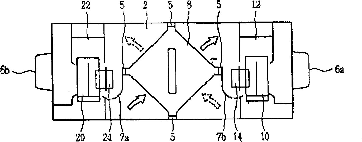
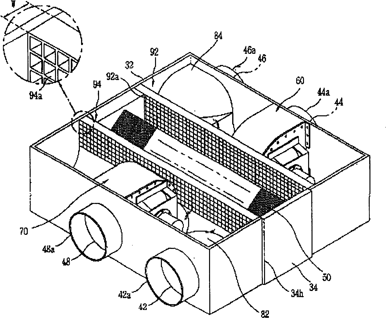
[0025] Hereinafter, preferred embodiments according to the present invention will be described in detail with reference to the accompanying drawings. image 3 and Figure 4 It is a perspective view and a schematic plan view of the ventilation device according to the present invention; Figure 5 It is a three-dimensional schematic diagram of another embodiment of the constant flow device of the ventilation device according to the present invention; Image 6 and Figure 7 for Figure 4 A schematic cross-sectional view along line A-A and line B-B.

[0026] Such as image 3 and Figure 4 As shown, an outdoor air suction hole 42 for sucking in outdoor air and a room air discharge hole 48 for discharging indoor air are formed on one side of a rectangular housing 32, and an outdoor air discharge hole 44 and a suction hole for discharging outdoor air are formed on the other side of the housing 32. Indoor air suction holes 46 for indoor air; across the center of the casing 32 is ...


PUM


Abstract

The present invention relates to one kind of air exchange device. In the space exhausting outdoor air or indoor air from the heat exchanger inside the casing, one flow stabilizer is set to change the flow of the outdoor air or indoor air from the heat exchanger into laminar flow so as to homogenize the flow of outdoor air or indoor air in the heat exchanger and to raise heat exchange efficiency.

Description

technical field [0001] The present invention relates to a ventilating device, in particular to a ventilating device in which outdoor air and indoor air become laminar flow after passing through a heat exchanger for heat exchange to improve air supply efficiency and heat exchange efficiency . The above-mentioned ventilation device sucks the outdoor air into the room and discharges the indoor air to the outside, so that heat exchange is performed between the indoor air and the outdoor air, and the air in the indoor space is ventilated to maintain a comfortable environment. Background technique [0002] Typically, the air in an enclosed space has an elevated carbon dioxide content over time due to the respiration of living organisms. When the carbon dioxide content increases, the breathing of the living body will be uncomfortable, so the ventilation device is often used in narrow spaces with many people such as offices and vehicles to replace indoor polluted air with fresh out...

Claims


Application Information

Patent Timeline
Patent Type & Authority Patents(China)
IPC IPC(8): F24F7/08F24F13/08
Inventor 赵民哲沈秀延李成焕
Owner LG ELECTRONICS (TIANJIN) APPLIANCES CO LTD
Why Eureka
Try Eureka