Cartridge and image forming apparatus

A technology of imaging equipment and process box, which is applied in the field of process box and imaging equipment, and can solve problems such as inability to prevent toner leakage

Active Publication Date: 2008-12-03
BROTHER KOGYO KK
View PDF5 Cites 0 Cited by
  • Summary
  • Abstract
  • Description
  • Claims
  • Application Information

AI Technical Summary

Problems solved by technology

However, when the position of the process cartridge is changed when the process cartridge is assembled to the apparatus main body and placed on a horizontal surface, for example, when the process cartridge is attached to the apparatus main body with the opening facing downward, the above structure cannot prevent discoloration. powder spill

Method used


Image

  • Cartridge and image forming apparatus
  • Cartridge and image forming apparatus
  • Cartridge and image forming apparatus

Examples


Embodiment Construction

[0034] Example

[0035] Some aspects of the present invention will be described with reference to FIGS. 1 to 12.

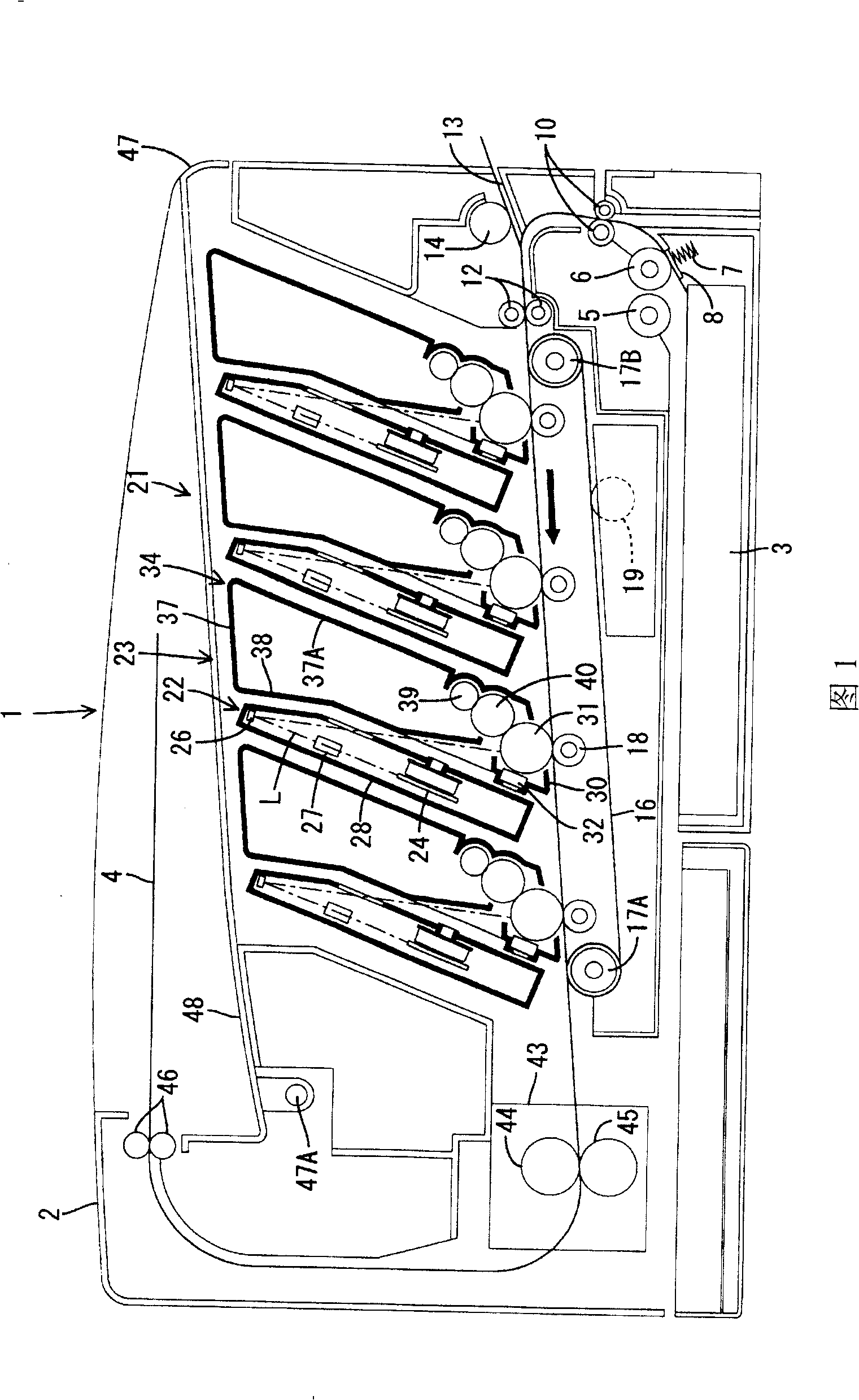
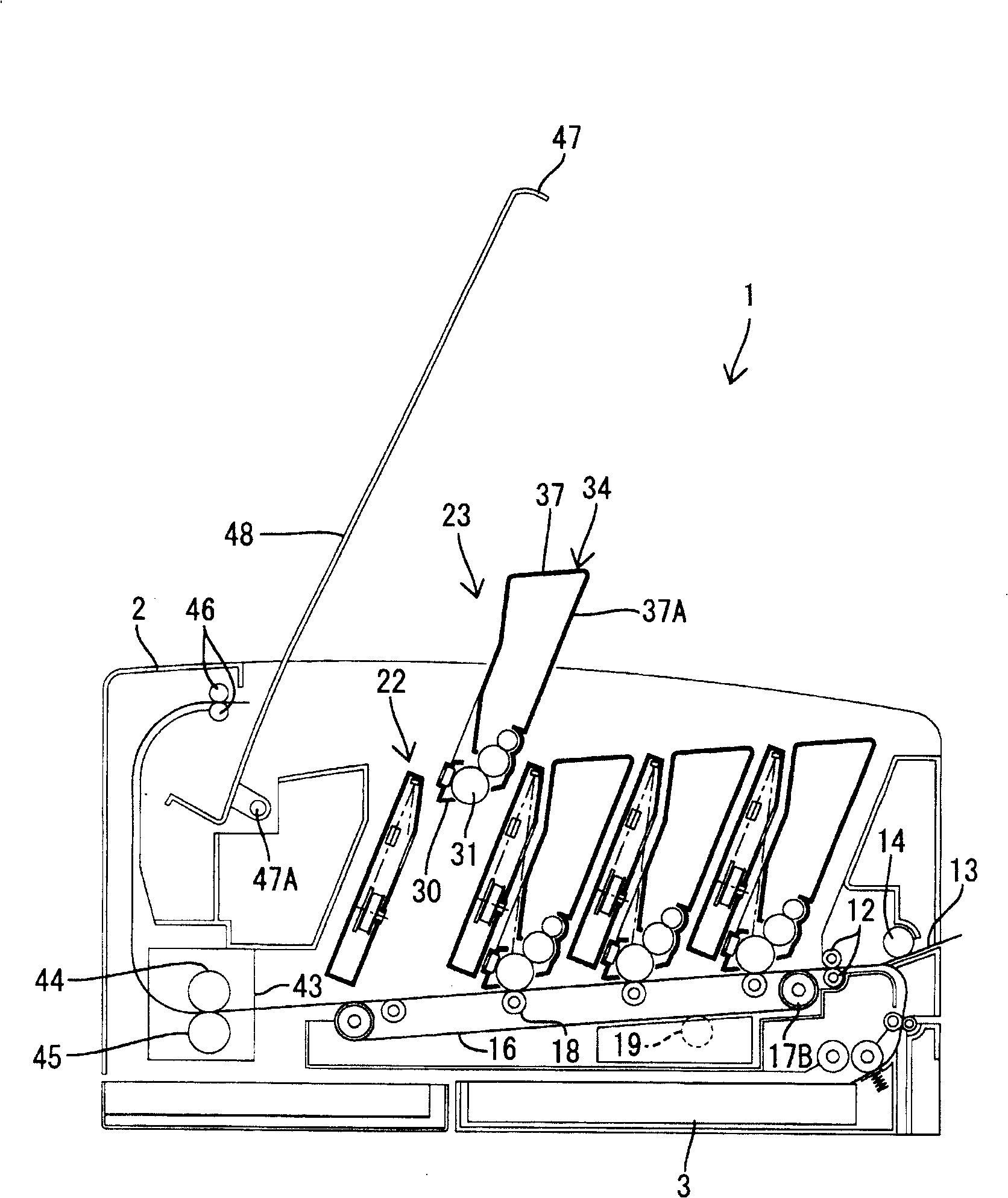
[0036] FIG. 1 is a side sectional view of the overall structure of a laser printer 1 as an image forming apparatus according to some aspects of the present invention. The laser printer 1 is a direct tandem color laser printer, and has four photosensitive drums 31 corresponding to black, cyan, magenta, and yellow, respectively. In the following description, the right side in Figure 1 is referred to as the front side.

[0037] The laser printer 1 includes a paper supply tray 3 in the lower part of the main body casing 2. The paper feed tray 3 is detachably attached to the main body casing 2 from the front side. The paper supply tray 3 is configured to supply a stack of paper 4 for imaging. A platen (not shown) is provided at the bottom of the paper supply tray 3 and is configured to lift the front end of the paper 4. The pickup roller 5 and the paper feed roller 6 arran...


PUM


Abstract

A toner receiving member, which is open upward, is provided at a position vertically below a lower end of a contact surface between a side seal member and a developing roller. The toner receiving member can receive and store toner which has leaked. In addition, when a developing cartridge is removed from a main body casing and then placed on a horizontal surface such as a desktop, a front wall, which serves as a bottom surface of the toner receiving member, faces upward. Toner collected in the toner receiving member may be prevented from leaking.

Description

[0001] Cross-reference of related applications [0002] This application claims priority to Japanese Patent Application 2004-285162 filed on September 29, 2004, the entire subject matter of which is incorporated herein by reference. Technical field [0003] The invention relates to a processing box and an imaging device containing the processing box. Background technique [0004] The electrophotographic image forming apparatus may be provided with a process cartridge including a developing device. The process cartridge is designed to be detachably attached to the main body of the image forming apparatus. The process cartridge includes a housing that stores toner as a developer and a developing roller, and the developing roller is rotatably installed in an opening formed in the housing. The developing roller is designed to form a visible image by transferring a thin layer of toner formed on the developing roller to an electrostatic latent image formed on the photosensitive drum. Th...

Claims


Application Information

Patent Timeline
Patent Type & Authority Patents(China)
IPC IPC(8): G03G15/06G03G15/00
CPCG03G15/0817G03G2221/1648
Inventor 福田纮也
Owner BROTHER KOGYO KK
Why Eureka
Try Eureka