Chain transmission device

A technology of chain drive and toothed chain, applied in the direction of transmission device, transmission chain, belt/chain/gear, etc., can solve the problems such as difficulty in achieving high chain strength, large extension of connecting pin and roller chain, and difficulty in disengaging from meshing. Achieve the effect of lightweight reduction, noise suppression, and smooth bending motion

Inactive Publication Date: 2009-04-29
TSUBAKIMOTO CHAIN CO
View PDF1 Cites 2 Cited by
  • Summary
  • Abstract
  • Description
  • Claims
  • Application Information

AI Technical Summary

Problems solved by technology

[0005] The chain drive using the above-mentioned known silent chain is advantageous in that the silent chain has higher strength and lower noise than the roller chain. On the contrary, since the pin hole of the link plate and the connecting pin rotate and slide, there The elongation caused by wear and tear is larger than that of the roller chain. In addition, the roller chain of the chain drive using the well-known roller chain has good fatigue strength and wear resistance elongation. On the contrary, the high strength of the roller It becomes a bottleneck and it is difficult to increase the strength of the chain, and since the roller directly enters the bottom side of the sprocket teeth during meshing, there is a problem that the meshing of the sprocket is louder than that of a silent chain
[0006] In addition, the above-mentioned conventional compound chain transmission device has a structure in which a roller chain with rollers is arranged in the center of the compound chain, and a silent chain is arranged on both outer sides. Since four link plates of the roller chain are arranged in the chain width direction, And the 4-piece link plate of the silent chain, so there is a problem that the chain width becomes larger and the mass of the chain itself becomes larger
Furthermore, in the silent chain, since the outer tooth flanks of the teeth of the link plate are not arc-shaped, there is a problem that the outer tooth flanks bite into the sprocket teeth and the engagement is difficult to disengage.

Method used


Image

  • Chain transmission device
  • Chain transmission device
  • Chain transmission device

Examples


Embodiment Construction

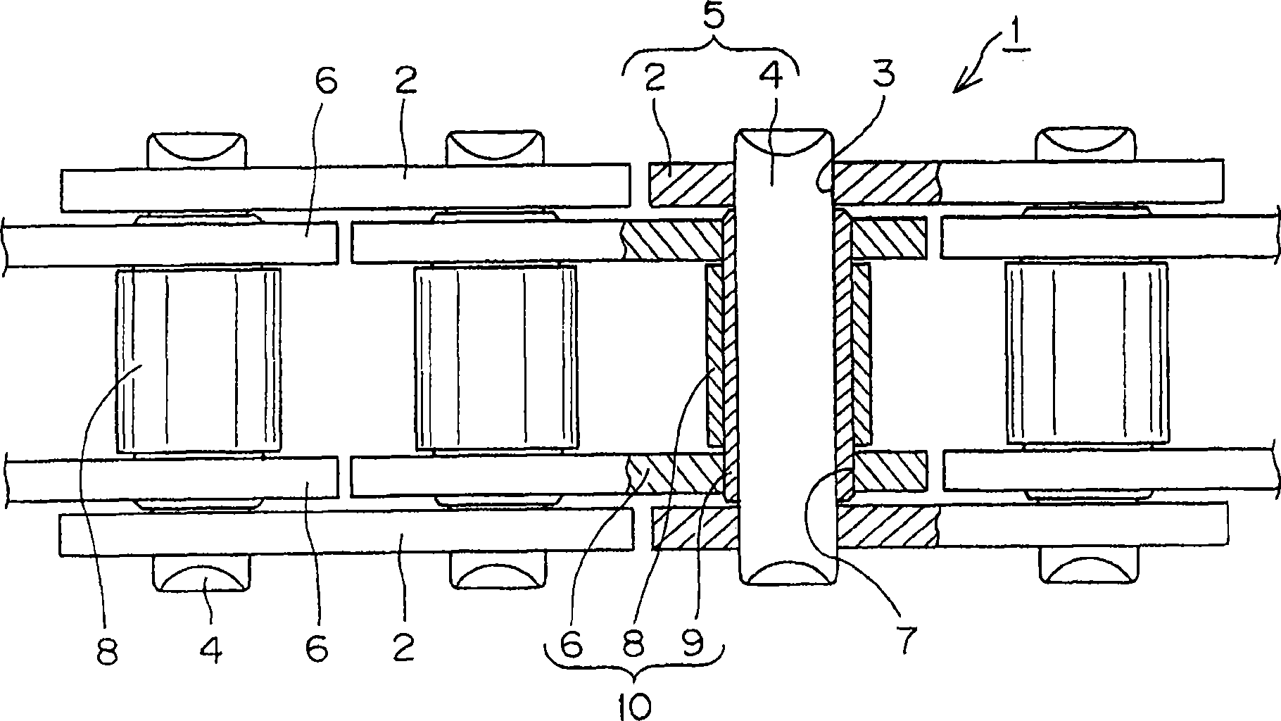
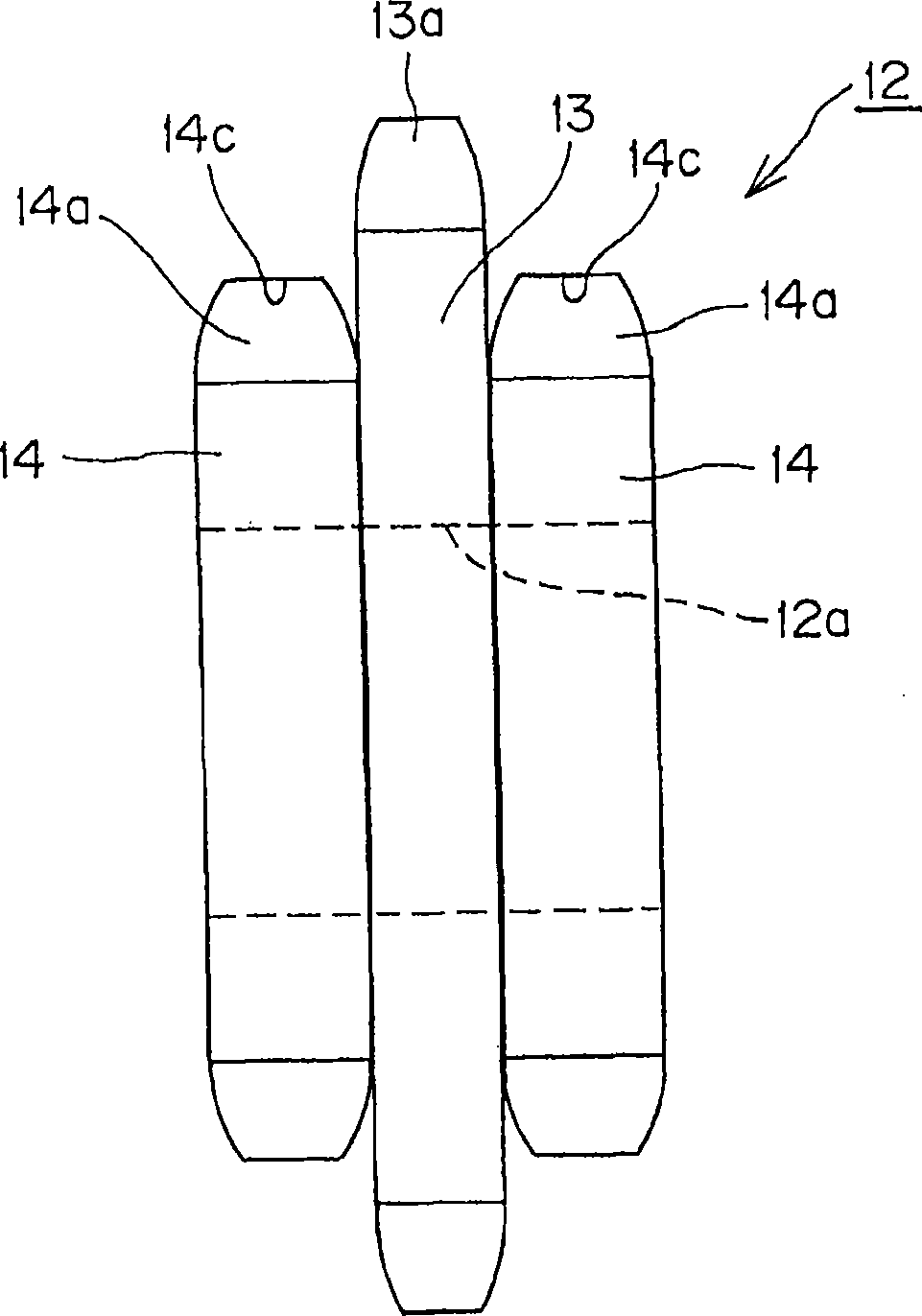
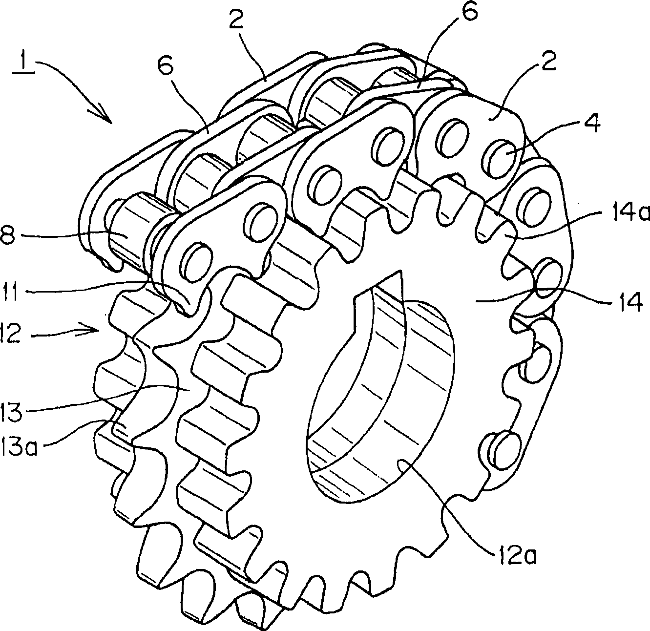
[0027] refer to Figure 1 to Figure 6 Example 1 of the present invention will be described. figure 1 It is a partial plan view showing the main part of the hybrid chain used in the chain transmission device of Embodiment 1 of the present invention in section, figure 2 is the front view of the compound sprocket, image 3 Represents a part of the chain transmission device, and is a perspective view showing the meshing state of the hybrid chain, Figure 4 is an explanatory diagram of the meshing state of the hybrid chain, Figure 5 yes Figure 4 A magnified view of part M of the Figure 6 Indicates the link plate used in the chain drive of the present invention, Figure 6 (A) is a chain link plate with teeth, Figure 6 (B) is a substantially elliptical link plate without teeth, Figure 6 (C) is a side view of a double-sided toothed link plate.

[0028] The chain transmission device (not shown) of this embodiment 1 is that each link plate of the outer link 5 and the inne...


PUM


Abstract

The present invention provides a chain transmission device which uses a hybrid chain which has the advantages of silent chain and the advantages of roller chain and other advantages of wear extending prevention, strength decreasing prevention, low noise realization and light weight realization. The chain transmission device is obtained through coiling the hybrid chain (1) on a complex sprocket (12), wherein the hybrid chain (1) is composed of an outer link (15) comprising a pair of outer link plate (2), and an inner link (10) comprising a pair of inner link plate (6) and a roller (8). The complex sprocket (12) is provided with a central sprocket (13) which is engaged with a roller (8), and a side sprocket (14). The link plates (2, 6) are provided with a pair of teeth (11). The outside flank (11a) of the teeth forms an air shape which takes the pin hole or sleeve hole at the far end of one pair of pin holes (3) or sleeve holes (7) of the link plates (2, 6) as a center.

Description

technical field [0001] The present invention relates to a chain transmission device that transmits power through a chain wound on a sprocket, such as a chain transmission device that is suitable for driving a driven shaft of a four-cycle engine's movable valve system or auxiliary equipment such as an oil pump. There are so-called roller chains and silent chains and hybrid chain chain transmissions with various functions. Background technique [0002] A chain transmission using a so-called roller chain or a chain transmission using a so-called silent chain is known. In addition, conventionally, there is known a compound chain transmission including a compound chain combining a silent chain and a roller chain, and a sprocket having teeth meshed with the compound chain (see Patent Document 1). [0003] The composite chain 37 used in the above-mentioned conventional composite chain transmission device is as follows: Figure 7 As shown, a roller chain 33 having rollers 34 is arr...

Claims


Application Information

Patent Timeline
Patent Type & Authority Applications(China)
IPC IPC(8): F16H7/06F16G13/06F16G13/04
CPCF16G13/06F16G13/02F16H55/30F16H7/06
Inventor 佐仓俊儿平井晶
Owner TSUBAKIMOTO CHAIN CO
Why Eureka
Try Eureka