Ink cartridge chip, ink cartridge, imaging device and method for replacing ink cartridge of imaging device

An ink cartridge chip and ink cartridge technology, which is applied in the field of ink cartridges, imaging devices and imaging device ink cartridge replacement, and ink cartridge chips, can solve problems such as wear, ink leakage equipment, and non-representation, and achieve the effect of simplifying machine recognition operations

Active Publication Date: 2010-08-18
APEX MICROELECTRONICS CO LTD
View PDF5 Cites 21 Cited by
  • Summary
  • Abstract
  • Description
  • Claims
  • Application Information

AI Technical Summary

Problems solved by technology

[0004] There are following defects in the above-mentioned prior art ink cartridge usage technology: the remaining amount of ink obtained by estimating does not represent the real ink amount, and for disposable ink cartridges, there may be ink that has not been used up, so there is no need to replace the ink cartridge at this time; The ink supply cartridge has realized that ink can be added to the ink cartridge through the ink delivery pipeline without pulling out the ink cartridge, so there is no need to replace the ink cartridge
[0007] Many printers currently in use have set such recognition requirements. Due to the inherent design limitations of the built-in program, when using a continuous supply ink cartridge that does not need to be replaced, the ink cartridge cannot be reused even if the ink cartridge chip is reset. Execute ink cartridge insertion and removal
Unnecessary ink leakage or equipment wear may occur during cartridge insertion and removal

Method used


Image

  • Ink cartridge chip, ink cartridge, imaging device and method for replacing ink cartridge of imaging device
  • Ink cartridge chip, ink cartridge, imaging device and method for replacing ink cartridge of imaging device
  • Ink cartridge chip, ink cartridge, imaging device and method for replacing ink cartridge of imaging device

Examples


Embodiment 1

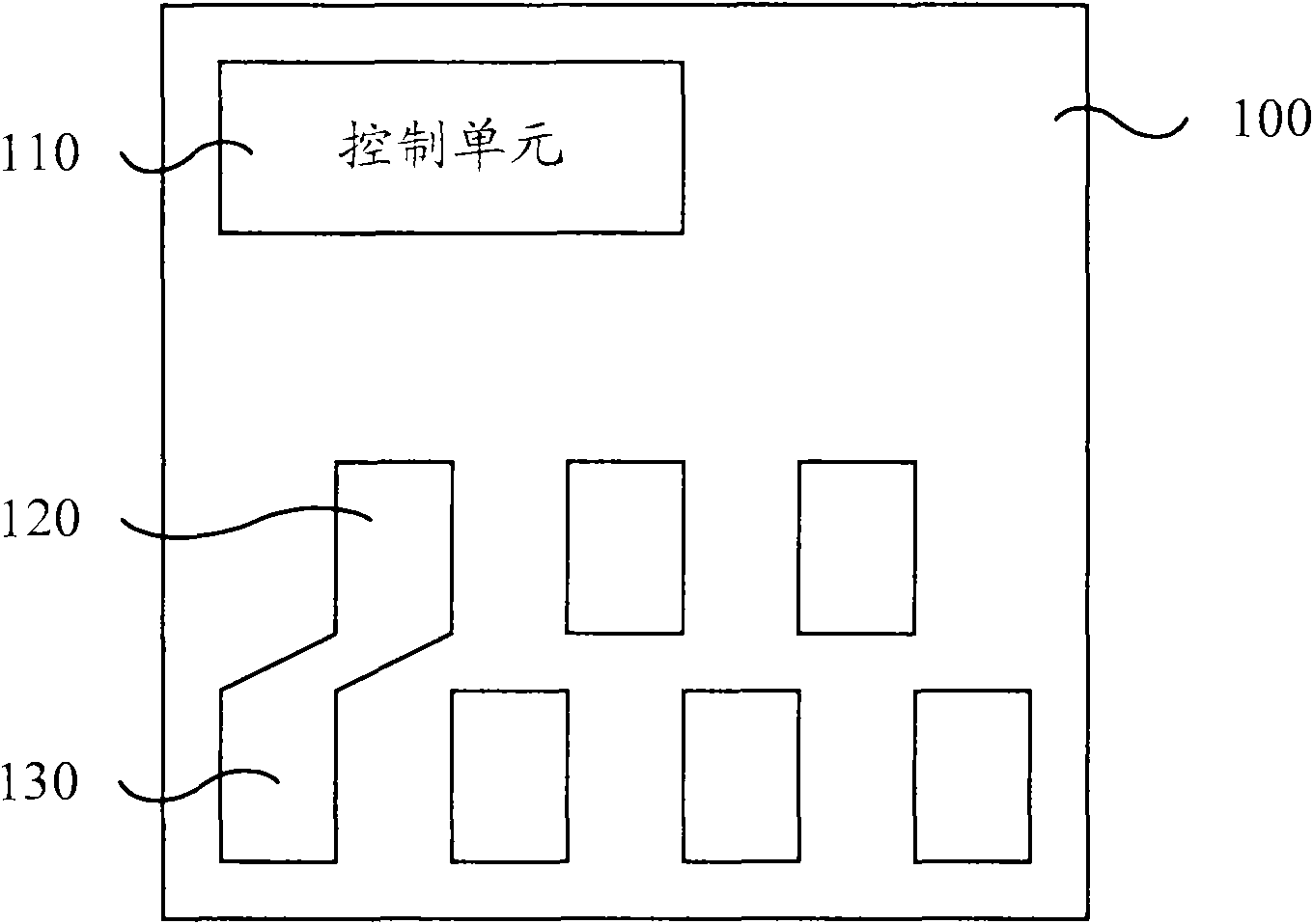
[0052] Figure 2A It is a schematic structural diagram of the ink cartridge chip provided by Embodiment 1 of the present invention, Figure 2A The diagram specifically shows the cooperation relationship between the ink cartridge chip and the main circuit of the imaging device. The embodiment of the present invention still uses the printer as an example for illustration, but those skilled in the art can understand that this technology can also be applied to other imaging devices using ink cartridges. scheme, and the ink cartridge is not limited to holding ink, it can be broadly interpreted as a container for holding other recording media for imaging devices.

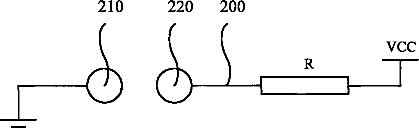
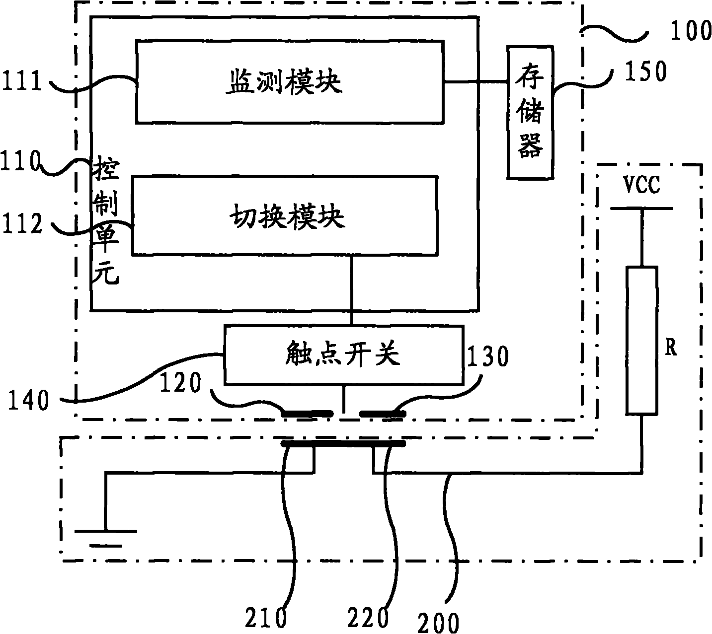
[0053] Such as Figure 2A As shown, the ink cartridge chip 100 in this embodiment includes a first contact 120 , a second contact 130 and a control unit 110 . Figure 2B It is a schematic diagram of the physical structure of the first contact and the second contact in Embodiment 1 of the present invention. Such as Fi...

Embodiment 2

[0071] Figure 4 The structural diagram of the ink cartridge chip provided by the second embodiment of the present invention, the difference between this embodiment and the first embodiment is that the monitoring module 111 includes an ink volume monitoring unit 111a, a reset unit 111b, a position monitoring trigger unit 111d, and a replacement position monitoring unit 111e and the second analog to replace the trigger unit 111f. Wherein, the ink quantity monitoring unit 111a is connected with the memory 150 storing the remaining ink quantity of the ink cartridge, or may also be connected with the sensor for detecting the remaining ink quantity of the ink cartridge, and is used to generate a reset signal when the remaining ink quantity is detected to reach a set threshold; reset The unit 111b is connected with the ink quantity monitoring unit 111a, and is used for performing the reset operation of the ink cartridge chip according to the reset signal; the position monitoring tri...

Embodiment 3

[0085] Figure 6 The structural diagram of the ink cartridge chip provided by Embodiment 3 of the present invention. The difference between this embodiment and Embodiments 1 and 2 is that the monitoring module 111 may include: an ink volume monitoring unit 111a, a reset unit 111b, a third analog replacement trigger unit 111g, Replace the position monitoring unit 111e and the fourth analog replacement trigger unit 111h. Wherein, the ink quantity monitoring unit 111a is connected with the memory 150 for storing the remaining ink quantity of the ink cartridge, or is connected with the sensor for detecting the remaining ink quantity of the ink cartridge, and is used to generate a reset signal when the remaining ink quantity is detected to reach a set threshold; the reset unit 111b It is connected with the ink volume monitoring unit 111a, and is used to perform the reset operation of the ink cartridge chip according to the reset signal; the third analog replacement trigger unit 111...


PUM


Abstract

The invention discloses an ink cartridge chip, an ink cartridge, an imaging device and a method for replacing the ink cartridge of the imaging device. The ink cartridge chip comprises a first contact, a second contact and a control unit and also comprises a contact switch which is arranged between the first contact and the second contact for switching on and off of the first and second contacts; the control unit comprises a monitoring module and a switching module, wherein the monitoring module is connected with the switching module for transmitting a trigger signal to the switching module when the trigger condition of the ink cartridge is monitored; and the switching module is connected with the monitoring module and the contact switch for controlling the contact switch to be turned on after being turned off when receiving the trigger signal. The ink cartridge chip, the ink cartridge, the imaging device and the method for replacing the ink cartridge of the imaging device provided by the invention can be suitable for the program design of an inherent imaging device by simulating plug and pull action of the ink cartridge so as to simplify the recognition operation of the imaging device.

Description

technical field [0001] The invention relates to an imaging device cartridge replacement technology, in particular to an ink cartridge chip, an ink cartridge, an imaging device and a method for replacing the ink cartridge of the imaging device. Background technique [0002] Imaging devices are common office equipment such as printers, copiers, and facsimile machines. The imaging device can be mainly divided into two parts: the main body of the imaging device and the ink cartridge. The ink cartridge is equipped with an ink cartridge chip, and the main body of the imaging device recognizes the information of the ink cartridge by identifying the ink cartridge chip. [0003] This article uses the printer as an example for explanation. When the ink cartridge is installed on the printer or the printer is turned on again, the control unit of the printer must perform a recognition process, that is, identify the ink cartridge chip. The control part of the printer will send a series ...

Claims


Application Information

Patent Timeline
Patent Type & Authority Applications(China)
IPC IPC(8): B41J2/175
Inventor 丁励曾梅莲祁美超
Owner APEX MICROELECTRONICS CO LTD
Why Eureka
Try Eureka