Check patentability & draft patents in minutes with Patsnap Eureka AI!

Brake system comprising a clutch shiftable by the brake pedal for disengaging the drive device from the piston-cylinder unit

A technology of braking device and driving device, applied in the direction of braking transmission device, hydraulic braking transmission device, brake, etc.

Inactive Publication Date: 2014-07-02
IPGATE
View PDF6 Cites 0 Cited by
  • Summary
  • Abstract
  • Description
  • Claims
  • Application Information

AI Technical Summary

Problems solved by technology

The problem with this solution is the piston seal, especially with the small piston diameters that are just preferred for the system

Method used


Image

  • Brake system comprising a clutch shiftable by the brake pedal for disengaging the drive device from the piston-cylinder unit
  • Brake system comprising a clutch shiftable by the brake pedal for disengaging the drive device from the piston-cylinder unit
  • Brake system comprising a clutch shiftable by the brake pedal for disengaging the drive device from the piston-cylinder unit

Examples


Embodiment Construction

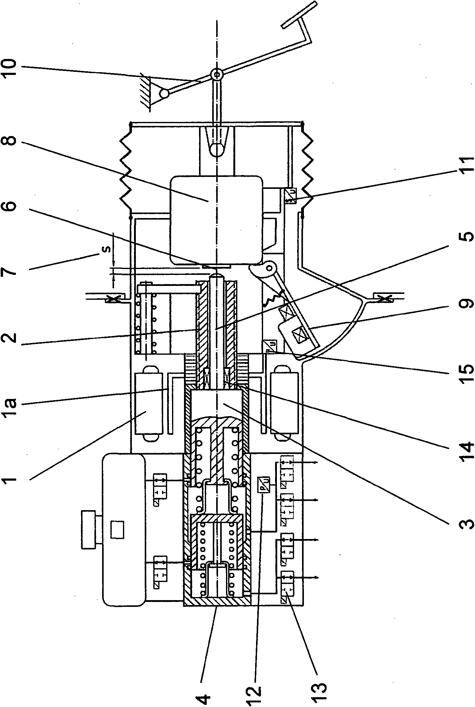
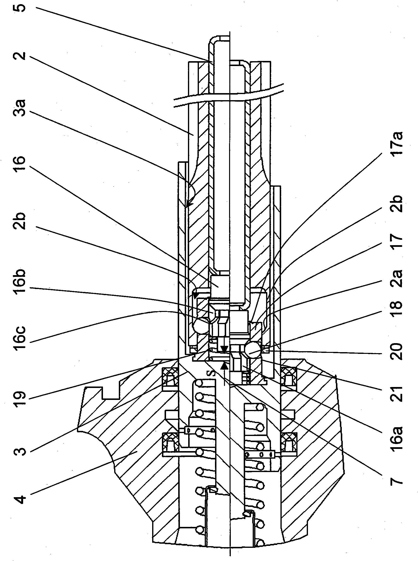
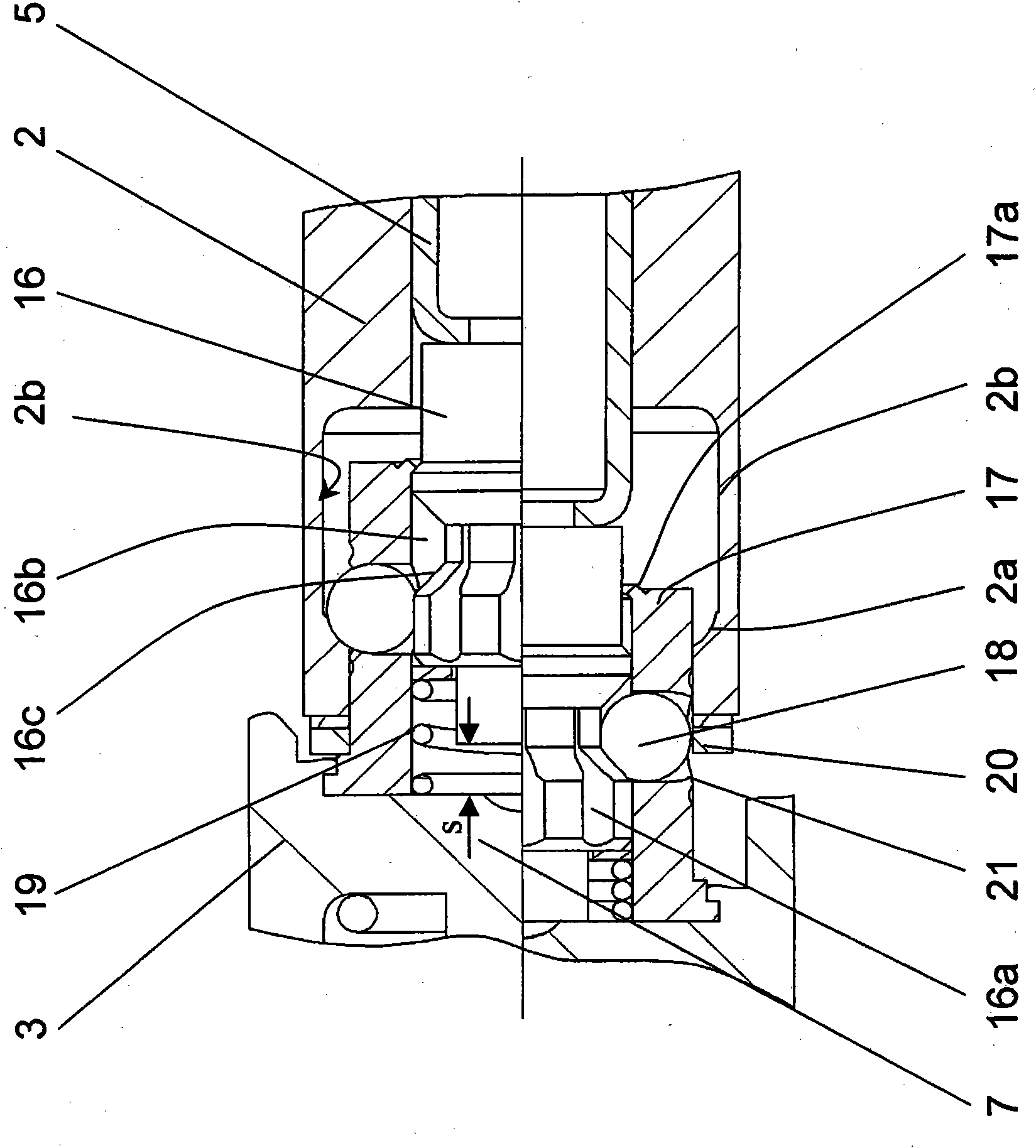
[0019] figure 1 An integrated brake booster with an electric motor 1 with an associated rotor 1 a driving a spindle nut 2 is shown. The plunger piston 3 is movably arranged in the tandem master cylinder 4 . The coupling element 14 acts between the piston 3 and the spindle 2 only during normal operation of the drive 1 . exist figure 1 The coupling itself and the connection between the piston 3, the main shaft 2 and the released or decoupled pedal rod 5 in the event of a fault are only schematically shown in the diagram and according to figure 2 to elaborate.

[0020] During normal operation, the actuation of the brake pedal 10 is detected by the pedal travel sensor 11 and pressure and relief are built up by the motor 1 by means of the spindle drive 5 of the plunger piston 3 . The principles of pressure build-up and decompression are sufficiently known from the documents described in this application as prior art. In this regard full reference is made to said document. Wi...


PUM


Abstract

The invention relates to a brake system, comprising at least one piston-cylinder unit for producing a pressure in at least one working chamber, the working chamber being connected to at least one wheel brake via at least one hydraulic line, and the brake system comprising at least one drive device and an actuating device, particularly in the form of a brake pedal, and the drive device during normal operation acting on the at least one first piston of the piston-cylinder unit for building pressure and reducing pressure by way of a first force transmission means, and in the event of failure of the drive device the actuating device acting mechanically on the piston by way of a second force transmission means, wherein the adjustment of the second force transmission means disengages the connection between the first force transmission means and the piston by means of the actuating device.

Description

technical field [0001] The invention relates to a brake device with at least one piston-cylinder unit for generating pressure in at least one working chamber, wherein the working chamber is connected to at least one wheel brake via at least one hydraulic line connected, and the braking device has at least one drive device and an actuating device in particular in the form of a brake pedal, and the drive device acts on at least one first piston of the piston-cylinder-unit during normal operation via a first force transmission mechanism For pressure build-up and decompression, and in the event of a fault, the actuating device acts mechanically on the piston via the second force transmission. Background technique [0002] In brake systems there is a tendency to replace vacuum brake boosters (V-BKV) by hydraulic or electric brake boosters (BKV). DE 10 2004 050 103 A1 describes an embodiment of an electric brake booster. Here, the pressure modulation takes place in a separate un...

Claims


Application Information

Patent Timeline
Patent Type & Authority Patents(China)
IPC IPC(8): B60T8/32B60T13/12B60T13/74
CPCB60T8/4077B60T11/18B60T13/745B60T13/00
Inventor 瓦伦丁·翁特尔弗罗纳海因茨·莱贝尔
Owner IPGATE
Features
  • R&D
  • Intellectual Property
  • Life Sciences
  • Materials
  • Tech Scout
  • Unparalleled Data Quality
  • Higher Quality Content
  • 60% Fewer Hallucinations
Learn More