Device for enhancing house illumination by using large plane mirror and manufacturing method thereof

A reflector and illuminance technology, which is applied in residential construction and other directions, can solve the problems of high cost, large amount of raw materials, complex structure, etc., and achieve the effect of low cost, high reflectivity, and improved light intensity.

Inactive Publication Date: 2011-06-22
XIANGMING MIDDLE SCHOOL SHANGHAI
View PDF0 Cites 1 Cited by
  • Summary
  • Abstract
  • Description
  • Claims
  • Application Information

AI Technical Summary

Problems solved by technology

The construction method of the building daylighting roof in the prior art has a complex structure, a large amount of raw materials used, and a high cost, and cannot provide good light for the building in front of the building.

Method used


Image

  • Device for enhancing house illumination by using large plane mirror and manufacturing method thereof
  • Device for enhancing house illumination by using large plane mirror and manufacturing method thereof
  • Device for enhancing house illumination by using large plane mirror and manufacturing method thereof

Examples


Embodiment 1

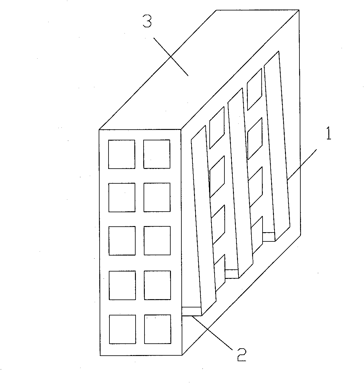
[0029] Please see attached figure 1 As shown, a device of the present invention that adopts a large plane reflector to improve the illuminance of a house includes a plane plate 1 and a support rod 2, the plane plate 1 is arranged on the outer wall of the house 3, and one end of the support rod 2 is arranged on the outside of the house 3 On the wall, the other end of the support rod 2 is arranged on the bottom of the flat panel 1, and the flat panel 1 is a reflector. The upper end is fixedly connected with the upper end of the outer wall of the house 3, and the angle range between the plane plate 1 and the outer wall of the house 3 is 20°-70°.

Embodiment 2

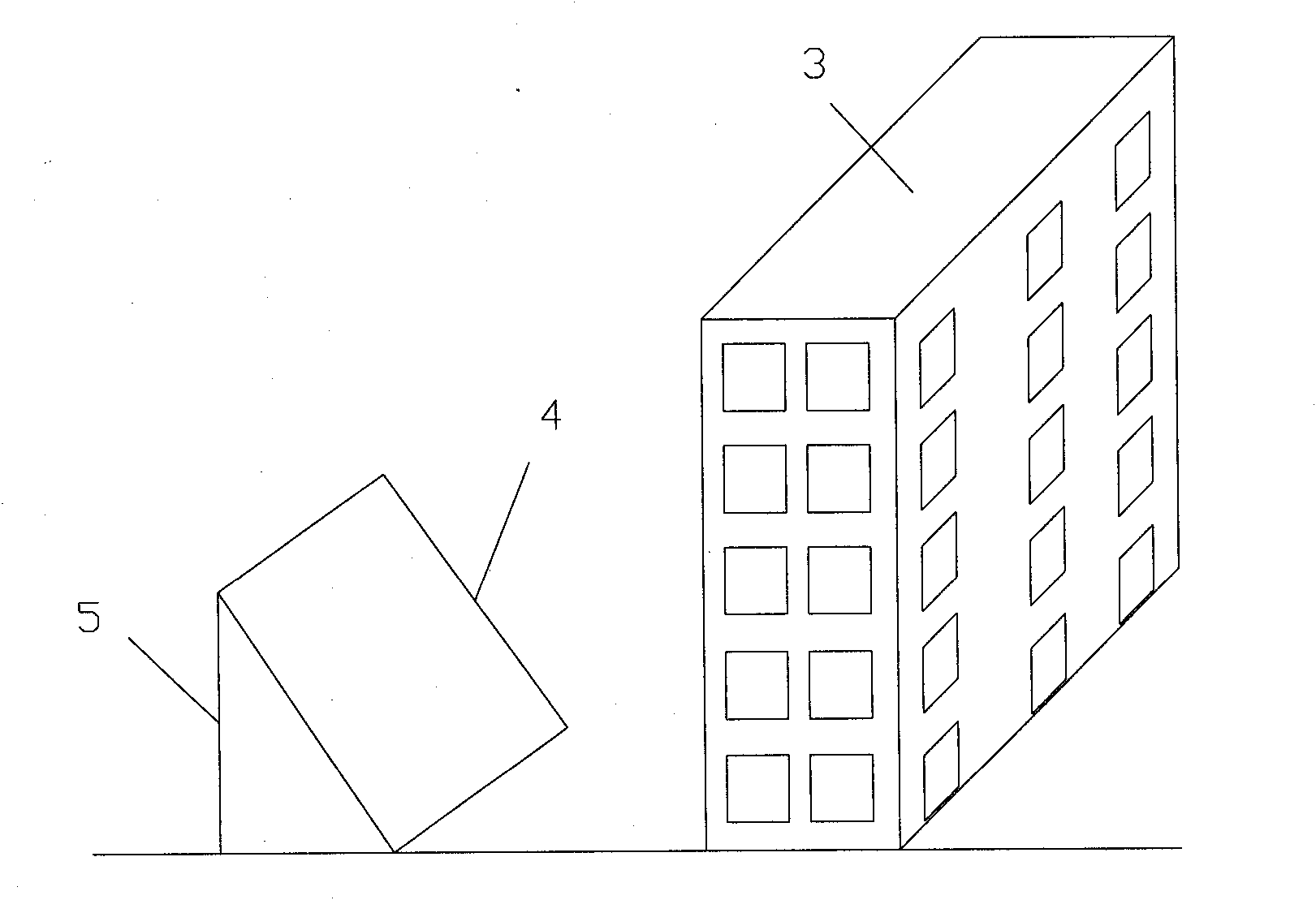
[0031] Please see attached figure 2 As shown, a device of the present invention that adopts a large plane reflector to improve the illuminance of a house includes a floor plank 4, which is placed on the ground and is located on the north side of the house 3. The floor plank 4 is a reflector, and the floor plank 4 4 placed toward the sun, for reflecting sunlight, a support column 5 is provided on the rear side of the floor plank 4, the upper end of the support column 5 is arranged in the center of the upper end of the floor plank 4, and the lower end of the support column 5 is vertically arranged on the ground. Because the landing plane plate 4 is obliquely arranged on the ground, the angle range between the landing plane plate 4 and the ground is 20°-70°.

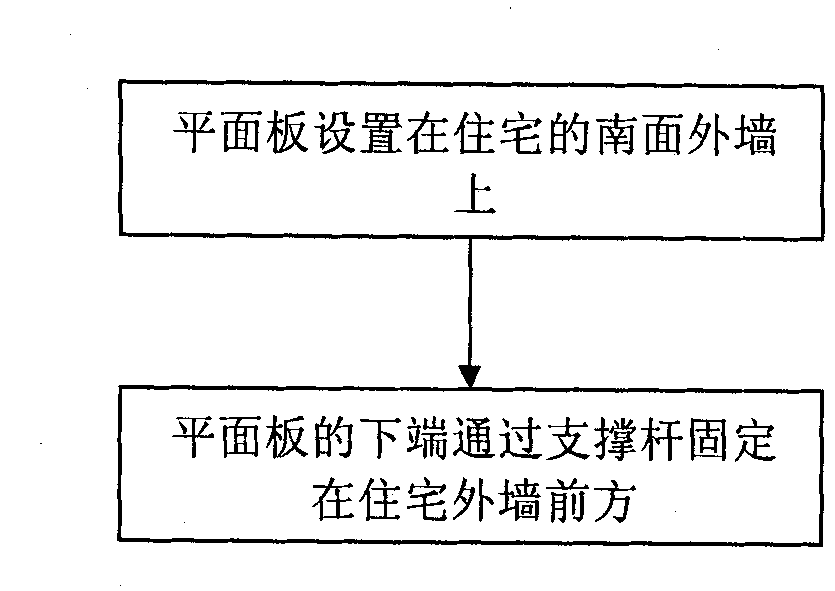
[0032] Please see attached image 3 Shown, a kind of manufacturing method of the device that adopts large-scale plane reflector to improve residential illuminance of the present invention, this method at least comprises t...


PUM


Abstract

The invention discloses a device for enhancing house illumination by using a large plane mirror, which comprises: a planar plate, which is arranged on the external wall of the house; and a pair of supporting rods, one end of each of which is arranged on the external wall of the house while the other end is arranged at the bottom end of the planar plate. The manufacturing method of the device for enhancing house illumination by using the large plane mirror comprises the steps of: 1, manufacturing the planar plate in a shape of long strip and placing the planar plate on the southern external wall of the house; and 2, fixing the lower end of the planar plate in front of the external wall of the house by the supporting rods. Owing to the light reflecting plate arranged, the device can reflect the sunlight into the room in front to enhance the intensity of illumination of the house facing north, can adjust the angle between the light reflecting plate and the house according to the sunlight illumination angles in different seasons to ensure high light reflectivity, and is simple in structure, convenient in use, low in cost, easy in popularization and application, and especially suitable for the use at the locations featured by dense houses, inferior natural lighting and north-facing houses.

Description

technical field [0001] The invention relates to a method for improving illumination, in particular to a device and a manufacturing method for increasing residential illumination by using a large plane reflector. Background technique [0002] Many high-rise residences face both south and north. Because the south faces the sun, the light is good, and the winter is warm, it is more popular than the north-facing buildings, but the price is often high. The south-facing houses can be used during the day. Natural light can save lighting electricity, while houses facing north have poor lighting and need to rely more on lighting than houses facing south. [0003] At present, a kind of building daylighting roof construction method of prior art comprises adopting several rods to be spliced ​​into a skylight frame, and then laying glass, (1), according to the overall size and shape of the daylighting roof, determine the type of rods and the quantity used respectively, Dimensions and sh...

Claims


Application Information

Patent Timeline
IPC IPC(8): E04H1/02
Inventor 李雨佳吴岑怡方雨晴黄曾新
Owner XIANGMING MIDDLE SCHOOL SHANGHAI
Why Eureka
Try Eureka