Remote controller adjusting infrared current by working voltage and method thereof
A working voltage, infrared technology, applied in the field of infrared remote control, can solve the problems of unstable power supply voltage, unusable remote controller, etc.
- Summary
- Abstract
- Description
- Claims
- Application Information
AI Technical Summary
Problems solved by technology
Method used
Image


Examples
no. 1 example
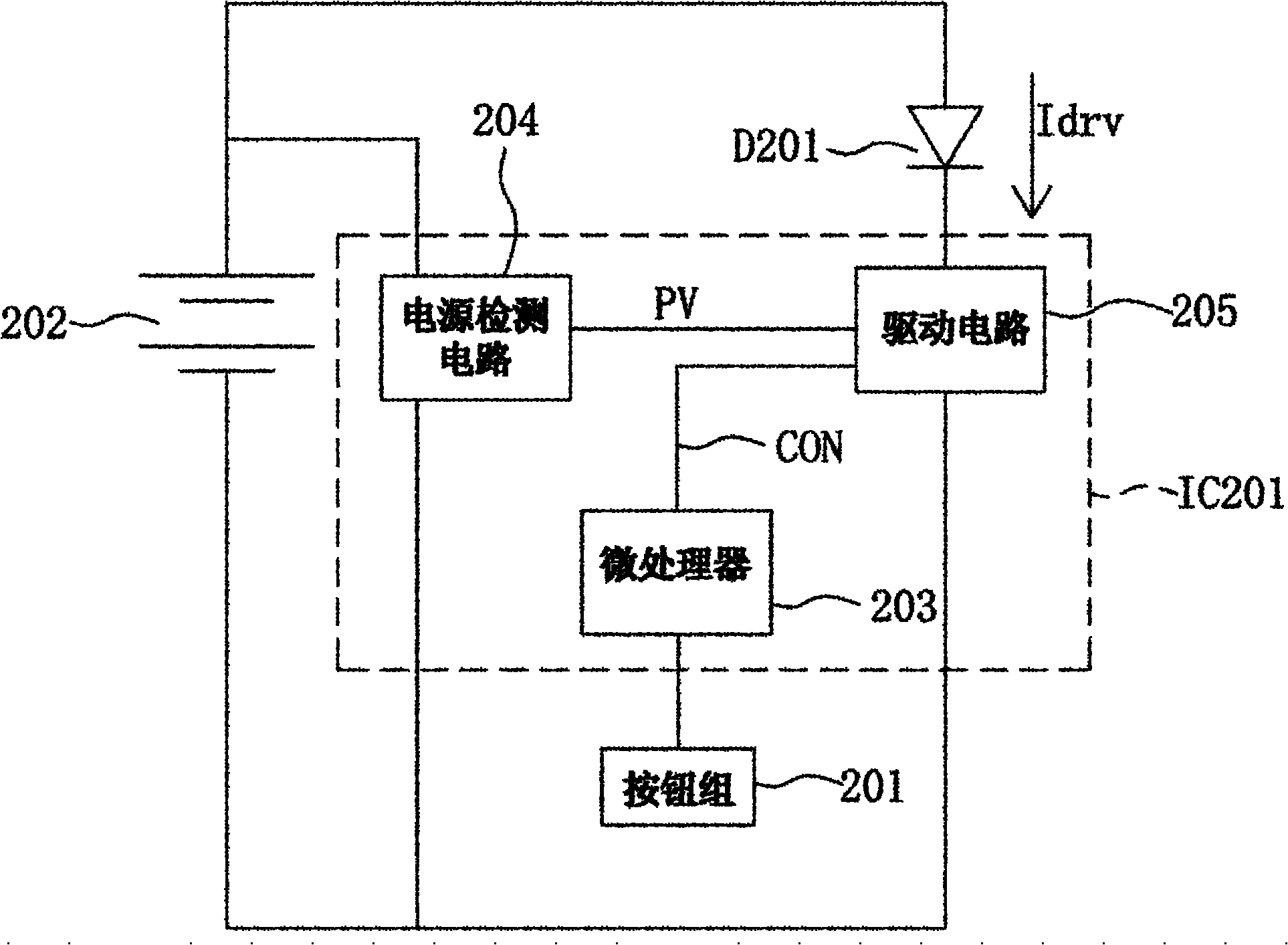
[0047] figure 2 It is a circuit block diagram of the remote controller for adjusting the infrared current through the working voltage according to the first embodiment of the present invention. Please refer to figure 2 , the infrared remote controller includes an infrared light emitting diode D201, a button group 201, a battery 202 and a remote controller control circuit IC201. The coupling relationship of the circuit of this remote control is as follows figure 2as shown. The battery 202 is used to supply a power supply voltage VDD to the remote controller control circuit IC201, the infrared light emitting diode D201, the button group 201 and other circuits. The anode of the infrared LED D201 is coupled to a power supply voltage VDD. The remote controller control circuit IC201 is coupled to both ends of the battery 202 to detect the magnitude of the power supply voltage and determine the magnitude of the current Idrv flowing through the infrared LED D201.
[0048] The ...
no. 2 example
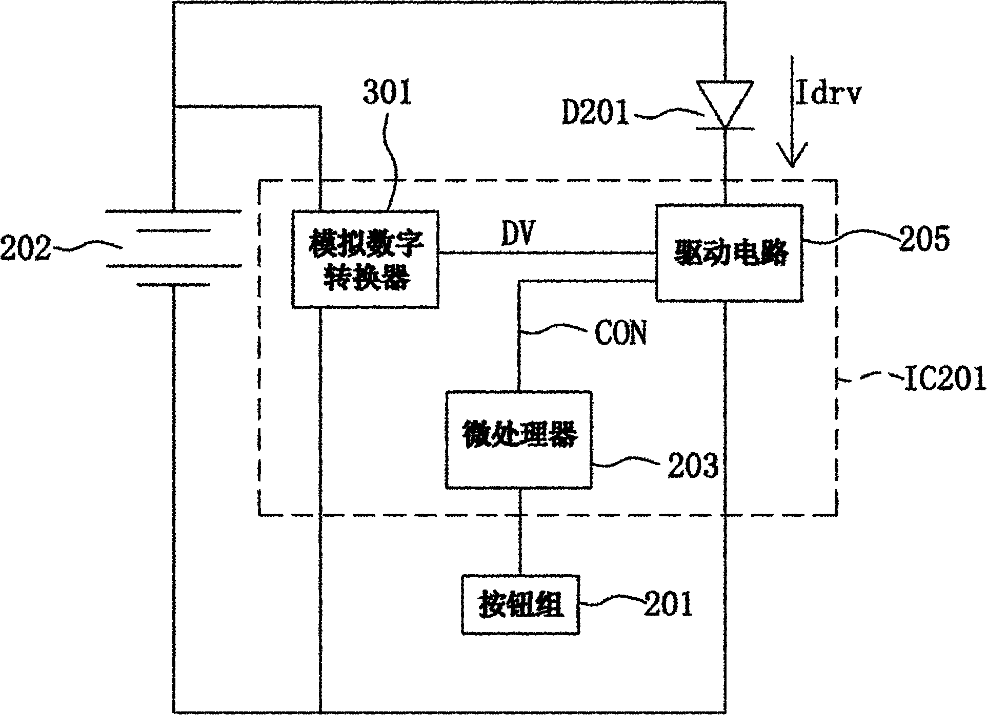
[0050] image 3 It is the circuit block diagram of the remote control for adjusting the infrared current through the working voltage according to the second embodiment of the present invention. Please refer to image 3 The difference between this second embodiment and the above-mentioned embodiments is that the power detection circuit 204 of this embodiment is implemented using an analog-to-digital converter 301 . The analog-to-digital converter 301 is used to convert the power supply voltage VDD of the battery into a digital value DV, and output it to the above-mentioned current-controlled LED output driving circuit 205 . The current-controlled LED output driving circuit 205 determines the magnitude of the maximum driving current Idrv flowing through the infrared LED D201 according to the magnitude of the received digital value DV. Generally speaking, the current-controlled LED output drive circuit 205 has a preset threshold value. When the digital value DV is greater than ...
no. 3 example
[0054] Figure 4 It is the circuit block diagram of the remote control for adjusting the infrared current through the working voltage according to the third embodiment of the present invention. Please refer to Figure 4 The difference between this third embodiment and the above-mentioned embodiments is that the power detection circuit 204 of this embodiment is implemented by using an amplifier 401 , a first resistor R401 , a second resistor R402 and a reference voltage generator 402 . One terminal of the first resistor R401 is coupled to the battery 202 to receive the power supply voltage VDD, and the second terminal of the first resistor R401 is coupled to the second resistor R402 and the positive terminal of the amplifier 401 . The other end of the second resistor R402 is connected to the other end of the battery 202 . The negative terminal of the amplifier 401 is coupled to the reference voltage generator 402 to receive the reference voltage VREF. When the power supply v...
PUM
 Abstract
Description
Claims
Application Information
 - R&D
- Intellectual Property
- Life Sciences
- Materials
- Tech Scout
- Unparalleled Data Quality
- Higher Quality Content
- 60% Fewer Hallucinations
Browse by: Latest US Patents, China's latest patents, Technical Efficacy Thesaurus, Application Domain, Technology Topic, Popular Technical Reports.
© 2025 PatSnap. All rights reserved.Legal|Privacy policy|Modern Slavery Act Transparency Statement|Sitemap|About US| Contact US: help@patsnap.com