Uterine cervical dilator

A technology for dilators and cervix, which can be used in dilators, surgery, etc., and can solve problems such as the firm connection of difficult rod-shaped structures

Inactive Publication Date: 2013-06-12
LIAONING AIMU MEDICAL SCI&TECH
View PDF6 Cites 2 Cited by
  • Summary
  • Abstract
  • Description
  • Claims
  • Application Information

AI Technical Summary

Problems solved by technology

[0003] The best way to use the cavity dilator is to have a long rod-shaped structure behind it, but the surface of the water-absorbing mate

Method used


Image

  • Uterine cervical dilator
  • Uterine cervical dilator
  • Uterine cervical dilator

Examples


Embodiment 1

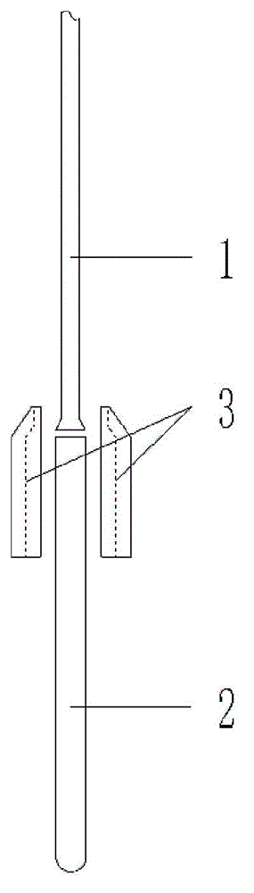
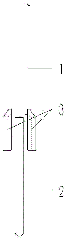
[0015] The cervical dilator is composed of a push rod 1 and a liquid-absorbing expansion material 2 fixed on the push rod 1, and a positioning block 3 is arranged at the joint between the push rod and the liquid-absorbing expansion material. The positioning block 3 is made of plastic material and is divided into symmetrical left and right halves. The two halves of the positioning block 3 are fused together by ultrasonic plastic welding, and the push rod 1 and the liquid-absorbing expansion material 2 are clamped at the same time.

Embodiment 2

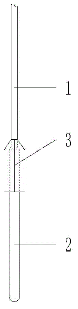
[0017] The cervical dilator is composed of a push rod 1 and a liquid-absorbing expansion material 2 fixed on the push rod 1 , and a positioning block 3 is arranged at the joint between the push rod 1 and the liquid-absorbing expansion material 2 . The positioning block 3 is made of plastic material and is divided into symmetrical left and right halves, one half of which is integrated with the push rod 1 , and the two halves of the positioning block 3 are fused together by ultrasonic plastic welding to clamp the liquid-absorbing expansion material 2 .


PUM


Abstract

The invention discloses a uterine cervical dilator, which comprises a push rod and a liquid absorption expansion material fixed to the push rod, wherein a positioning block is arranged at the joint of the push rod and the liquid absorption expansion material. According to the uterine cervical dilator, the liquid absorption expansion material can be locally closed under the clamping action of the push rod in an ultrasonic plastic welding way, so that liquid difficultly enters into the dilator in the using process and the purpose of structural safety is achieved.

Description

technical field [0001] The invention relates to a cervical dilator, in particular to a liquid suction expansion type cervical dilator. Background technique [0002] 201110235444.X discloses a water-absorbing material used in lumen dilators, and 201110235441.6 discloses a lumen dilator consisting of water-absorbing materials and tail wires. [0003] The better way to use the cavity dilator is to have a long rod-shaped structure behind it, but the surface of the water-absorbing material is super slippery after absorbing water, and it is difficult to make it firmly connected with a rod-shaped structure in general methods. Contents of the invention [0004] The object of the present invention is to provide a cervical dilator, which improves the structure of the lumen dilator. [0005] In order to achieve the above object, the cervical dilator of the present invention is composed of a push rod and a liquid-absorbing and expanding material fixed on the pushing rod, wherein, the...

Claims


Application Information

Patent Timeline
IPC IPC(8): A61M29/04
Inventor 武小锋
Owner LIAONING AIMU MEDICAL SCI&TECH
Why Eureka
Try Eureka