Positioning device of plate type movable supporting frame

A technology of movable support and positioning device, which is applied in the direction of packaging, transportation and packaging, and single objects. It can solve the problems of being unable to be lowered, affecting work efficiency, and affecting equipment, etc., and achieves the effect of facilitating employees to operate, improving work efficiency, and being easy to use.

CN103264784BActive Publication Date: 2015-03-25CHINA TOBACCO HENAN IND
7 Cites 0 Cited by

Patent Information

Authority / Receiving Office
CN · China
Patent Type
Patents(China)
Current Assignee / Owner
Publication Date
2015-03-25

Smart Images

  • Figure 1
    Figure 1
  • Figure 2
    Figure 2
  • Figure 3
    Figure 3
Patent Text Reader

Abstract

The invention discloses a positioning device of a plate type movable supporting frame. The positioning device comprises a lower fixing slide rail device fixedly connected to an encasement table supporting leg, and a lower sliding ring arranged on the lower fixing slide rail. A positioning rod is arranged in the lower sliding ring in a penetrating and sliding mode, and a clamping groove adaptive to the plate type movable supporting frame is arranged on the top of the positioning rod. A ring-shaped groove is arranged in the middle of the positioning rod, and a connection ring is arranged on the positioning rod at the ring-shaped groove in a sliding and sleeved mode. The connection ring is provided with a positioning board in a radial direction, and a ring clamp is fixedly connected to the encasement table supporting leg between the lower fixing slide rail device and the plate type movable supporting frame. The ring clamp is provided with a supporting groove used for clamping the connection ring positioning board. The positioning device of the plate type movable supporting frame is simple in structure, convenient to use, and capable of effectively solving the problem of horizontal wobbling of the movable supporting frame on the surface of a workbench of a stainless steel table in a cigarette encasement process. Personnel can conveniently operate, after the positioning device is used, cigarette encasement work can be carried out smoothly without adding manual work and lowering the operation speed of a cigarette packer, and therefore working efficiency can be improved.
Need to check novelty before this filing date? Find Prior Art

Description

technical field

[0001] The invention relates to the technical field of cigarette production, in particular to a positioning device for a plate-type movable support frame for cartoning cigarettes. Background technique

[0002] The width of the manual box case brought by the original cartoning and sealing machine in the workshop of the tobacco factory is not enough, and it is only about 30-40cm from the cigarette bar to the edge of the table. When the cigarette packaging equipment is in normal operation and manual boxing is performed, due to the high speed of the cigarette packaging equipment and the short boxing channel, when one person performs the boxing operation, the cigarettes often fail to be filled and the cigarettes fall on the ground. The current solution is to use two people to pack boxes at the same time or reduce the speed of the cigarette packaging machine. However, these existing solutions lead to increased labor costs or decreased equipment efficiency, and cann...

Examples

Embodiment Construction

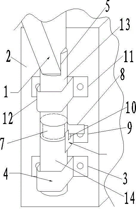
[0013] Such as Figure 1 to Figure 3 As shown, the plate-type movable support frame positioning device of the present invention includes a lower fixed slideway device 3 fixedly connected to the supporting legs 2 of the packing table by screws, and a lower slide ring 4 is provided on the lower fixed slideway device 3 .

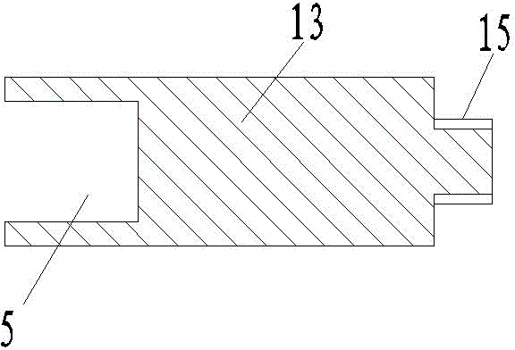
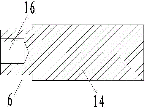
[0014] The sliding ring 4 is provided with a positioning rod, the top of the positioning rod is provided with a card slot 5 that is compatible with the plate type movable support frame 1, the middle of the positioning rod is provided with an annular groove 6, and the positioning rod at the annular groove 6 is slidingly sleeved. There is a connecting ring 7, and the connecting ring 7 is radially protrudingly provided with a positioning plate 8, and the distance between the outer end of the positioning plate 8 and the axis of the positioning rod is greater than the outer diameter of the sliding ring 4, so when the positioning rod falls downward, the sliding The r...