AI technical title is built by PatSnap AI team. It summarizes the technical point description of the patent document.
A heat pump system, electromagnetic technology, applied in the electromechanical field, can solve the problem of low heating efficiency
Inactive Publication Date: 2015-08-05
HARBIN INST OF TECH
View PDF6 Cites 0 Cited by
Summary
Abstract
Description
Claims
Application Information
AI Technical Summary
This helps you quickly interpret patents by identifying the three key elements:
Problems solved by technology
Method used
Benefits of technology
Problems solved by technology
[0003] The purpose of the present invention is to solve the problem of low heating efficiency of the heat pump system in the prior art in the environment of low temperature or lack of low temperature heat source, and provides a rotary electromagnetic heat pump system
Method used
Image
Click on the blue label to locate the original text in one second.
Reading with bidirectional positioning of images and text.
Examples
specific Embodiment approach 1
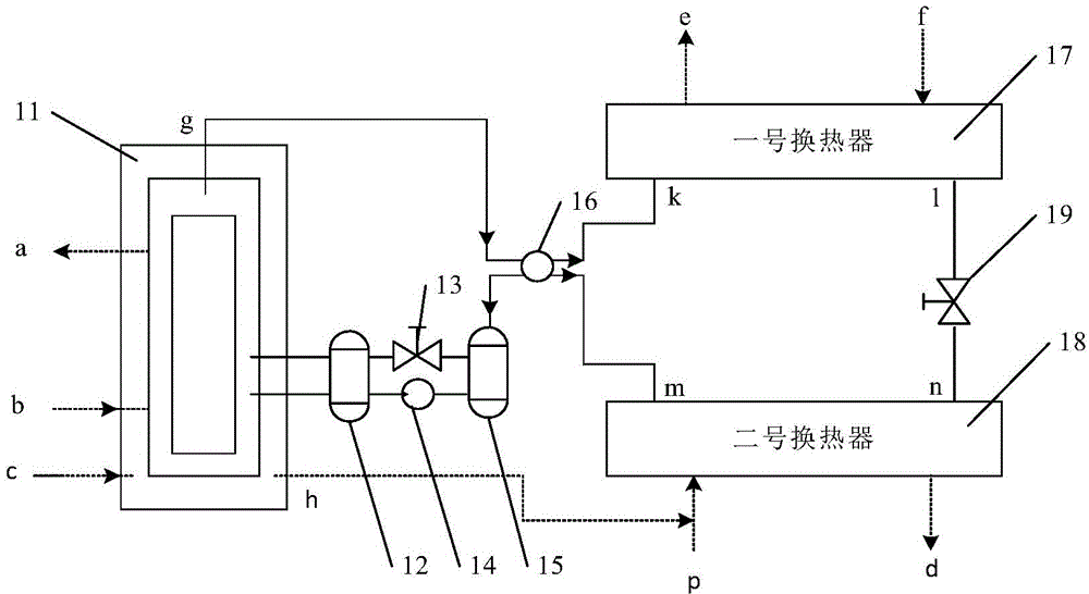
[0027] Specific implementation mode one: the following combination figure 1 Describe this embodiment, a rotary electromagnetic heat pump system described in this embodiment, which includes a rotary electromagnetic generator 11, a solution heat exchanger 12, a throttle valve 13, a solution pump 14, an absorber 15, and a four-way valve 16 , No. 1 heat exchanger 17, No. 2 heat exchanger 18 and No. 2 throttle valve 19;
[0028] The rotating electromagnetic generator 11 is provided with an external gas inlet a, an external gas outlet b, an external medium inlet c, an external medium outlet h, two working medium inlets and one working medium outlet;
[0029] The working fluid outlet g of the rotating electromagnetic generator 11 is connected to the No. 1 interface of the four-way valve 16;
[0030] The No. 1 heat exchanger 17 is provided with an external liquid medium outlet e, an external liquid medium inlet f, a working medium inlet and a working medium outlet;
[0031] The No. ...
specific Embodiment approach 2
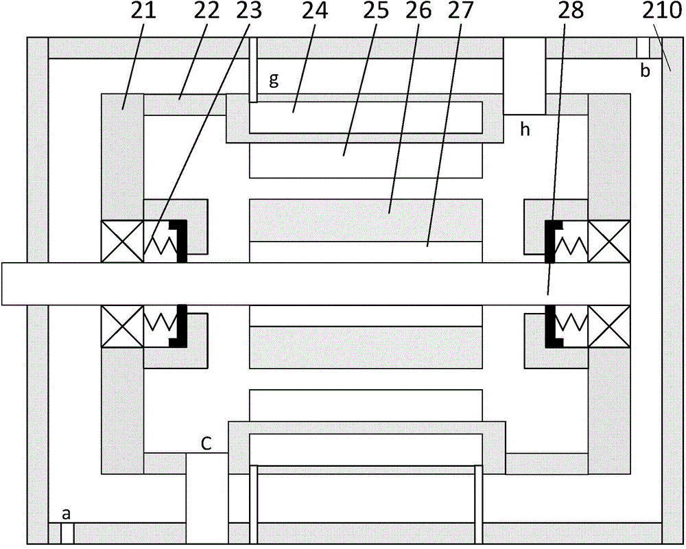
[0041] Specific implementation mode two: the following combination figure 1 , figure 2 with image 3 Describe this embodiment, this embodiment will further explain Embodiment 1, a rotary electromagnetic heat pump system described in this embodiment, the rotary electromagnetic generator 11 includes two end covers 21, a housing 22, a bearing and a sealing assembly 23. The stator, the rotor, the rotating shaft 28 and the heat preservation shell 210 are composed; the end cover 21 is a disc-shaped end cover, and the shell 22 is a cylindrical shell;
[0042] The two end covers 21 are installed at both ends of the casing 22 respectively, and the stator and the rotor are both arranged inside the casing 22;
[0043] The center of the end cover 21 is provided with a bearing seat; the bearing and sealing assembly 23 are fixedly installed in the bearing seat; the rotating shaft 28 is rotationally connected with the end cover 21 through the bearing and sealing assembly 23;
[0044] The...
specific Embodiment approach 3
[0054] Specific implementation mode three: the following combination Figure 4 Describe this embodiment, this embodiment will further explain Embodiment 1, a rotary electromagnetic heat pump system described in this embodiment, the stator core 25 is that M rectangular grooves are opened in the axial direction on the side wall of the inner ring The ring structure; the M rectangular grooves are evenly distributed on the side wall of the inner ring.
PUM
Abstract
The invention relates to a rotary electromagnetic heat pump system which belongs to the electromechanical field and aims to solve the problem that a heat pump system in prior art has low heating efficiency in a low-temperature condition or a condition lacking of a low-temperature thermal source. The rotary electromagnetic heat pump system comprises a rotary electromagnetic generator, a solution heat exchanger, two throttling valves, a solution pump, an absorber, a four-way valve and two heat exchangers, wherein an outside gas inlet, an outside gas outlet, an outside medium inlet, an outside medium outlet, two working medium inlets and one working medium outlet are formed in the rotary electromagnetic generator; the rotary electromagnetic generator generates heat through rotation, so as to heat a working medium; the working medium enters the heat exchanger for heat exchange with an outside medium after being gasified and separated out, and enters the other heat exchanger for heat absorption from the outside medium after heat transmission to the outside medium; after the outside medium is cooled, a refrigerant is heated and enters the rotary electromagnetic generator after passing through the absorber and the solution heat exchanger, so as to be heated again. Moreover, the rotary electromagnetic generator also can be used for directly heating the outside medium. The rotary electromagnetic heat pump system provided by the invention is applicable to fields in need of heating and cooling of the outside medium.
Description
technical field [0001] The invention relates to a rotating electromagnetic heat pump system, which belongs to the field of electromechanical. Background technique [0002] At present, a heat pump system usually includes a compressor, a condenser, a throttling device, an evaporator, and the like. During the heating process, the refrigerant in the evaporator absorbs the low-temperature heat in the air, water or other media, and becomes a high-temperature refrigerant after being processed by the compressor. The high-temperature refrigerant is transported to the refrigerant pipe of the condenser, and the refrigerant in the refrigerant pipe The high-temperature refrigerant heats the secondary refrigerant such as water in the water tank. It can be seen from the above that if the heat pump heating system operates in a low-temperature environment, or in an environment where low-temperature heat sources are scarce, the low-temperature refrigerant in the evaporator will obtain less h...
Claims
Application Information
Patent Timeline
Application Date:The date an application was filed.
Publication Date:The date a patent or application was officially published.
First Publication Date:The earliest publication date of a patent with the same application number.
Issue Date:Publication date of the patent grant document.
PCT Entry Date:The Entry date of PCT National Phase.
Estimated Expiry Date:The statutory expiry date of a patent right according to the Patent Law, and it is the longest term of protection that the patent right can achieve without the termination of the patent right due to other reasons(Term extension factor has been taken into account ).
Invalid Date:Actual expiry date is based on effective date or publication date of legal transaction data of invalid patent.

