Automatic turnover camera

A technology of automatic flipping and camera, applied in image communication, equipment, television, etc., can solve the problems of increasing product cost, not being able to realize self-portraits, and shooting effects that cannot satisfy people, and achieve the effect of saving production costs

Active Publication Date: 2014-07-23
GUANGDONG XIANGXIU RUI IND CO LTD
View PDF6 Cites 7 Cited by
  • Summary
  • Abstract
  • Description
  • Claims
  • Application Information

AI Technical Summary

Problems solved by technology

However, at present, the cameras of portable devices in the prior art are usually back-illuminated, which can hardly realize self-portraits. Even if some products can realize self-portraits, the shooting effect cannot satisfy people due to the low pixel of the camera.
In order to achieve a good selfie or video call effect, you can set the front camera, but this will greatly increase the cost of the product

Method used


Image

  • Automatic turnover camera
  • Automatic turnover camera
  • Automatic turnover camera

Examples


Embodiment 1

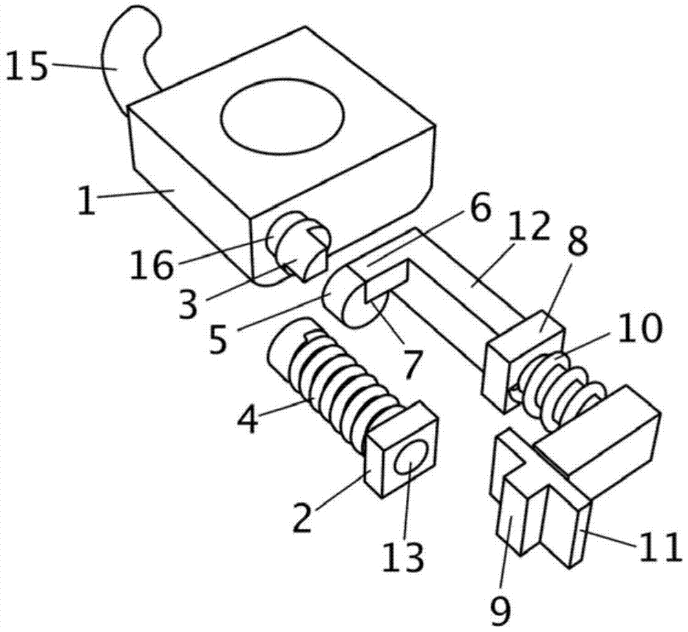
[0031] The automatic flip camera provided in this embodiment is as follows: figure 1 , Figure 6 to Figure 8 as shown in:

[0032] One side of the camera body 1 is connected to the first mounting end 2, the first mounting end 2 is provided with a through hole and fixedly connected with the mobile terminal device, the first mounting end 2 is provided with a connecting column 13, and one end of the connecting column 13 passes through the through hole Rotately connected with the first installation end 2, the other end of the connecting column 13 is fixedly connected with the limit block 5, the connecting piece 3, the rotating column 16, and the camera body 1 in sequence. The limit block 5 is provided with a limit groove 7, and the connecting column 13 is sleeved with a torsion spring 4, one end of the torsion spring 4 is fixed on the first installation end 2, and the other end is fixed on the connecting column 13. When the camera body 1 is not locked by the locking module, the...

Embodiment 2

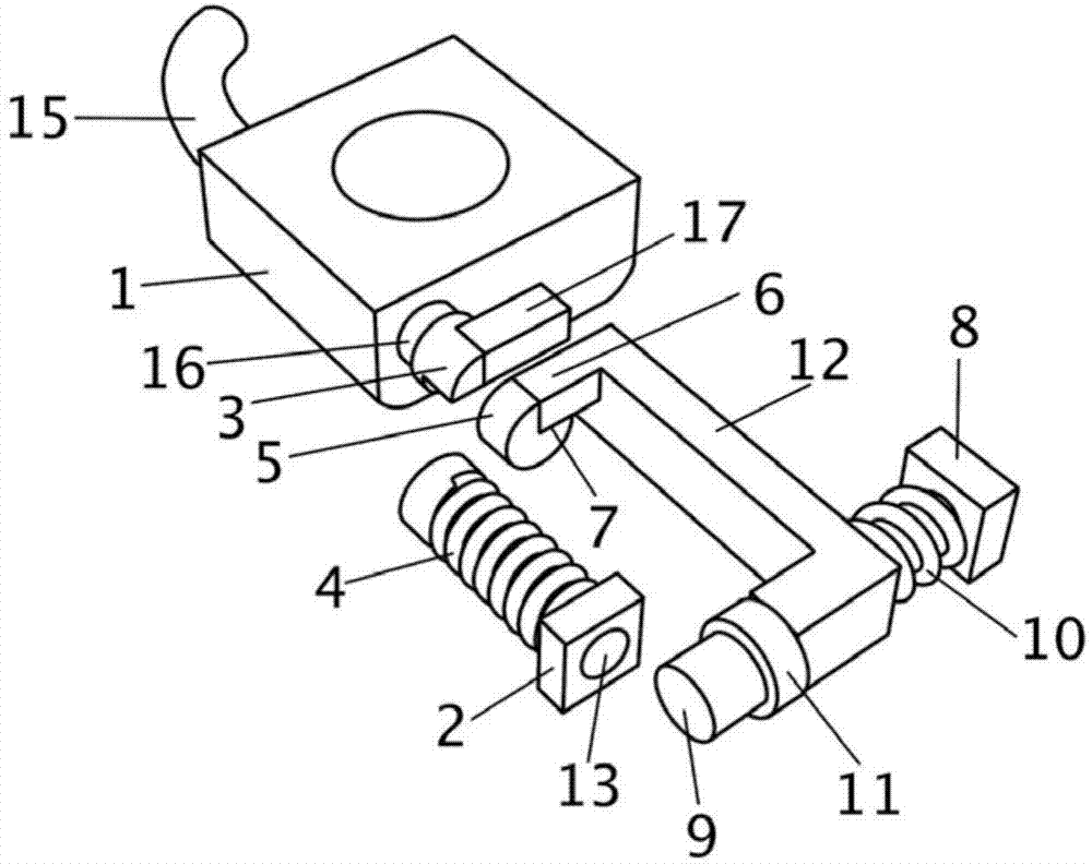
[0043] The automatic flip camera provided in this embodiment is as follows: figure 2 as shown in:

[0044] The structure of the automatic flip camera in this embodiment is similar to that of Embodiment 1, the only difference is that the movement direction of the limit post 6 of the locking module is perpendicular to the flip axis of the camera body 1, and the spring 10 connects the connecting rod 12 with the second Mounting end 8, the operating block 9 of this embodiment is a button type, and a brake block 17 is set in the mobile terminal device. The brake block 17 is rectangular, and its shape is similar to the limit post 6. When the camera body 1 is not overturned, A vertical end surface of the brake block 17 is aligned with the vertical surface of the connector 3 , and its bottom surface is at the same level as the bottom surface of the connector 3 .

[0045] By pressing the operation block 9, the limit column 6 can be driven out of the limit groove 7 via the connecting r...

Embodiment 3

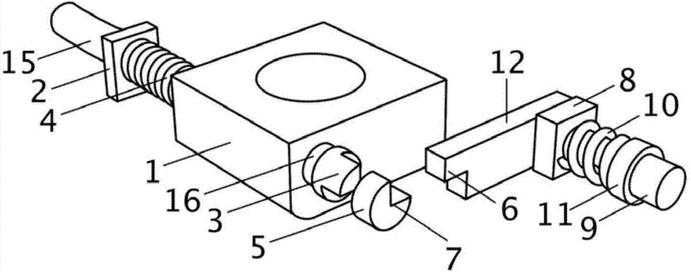
[0049] The automatic flip camera provided in this embodiment is as follows: image 3 as shown in:

[0050] The structure of the automatic flip camera in this embodiment is similar to that of Embodiment 1, the difference is that the connecting column 13 is fixedly connected with the camera body 1 with respect to the rotating column 16 on the other side of the fixed connecting piece 3 and the limit block 5, and The rotating column 16 and the connecting column 13 fixedly connected to the connecting column 13 are provided with lines, and the two ends of the line are respectively connected to the main line of the camera and the flexible line 15 connected to a terminal equipment. Connect with the connecting column 13 in the same manner as in Embodiment 1; the integral structure of the limiting column 6 and the connecting rod 12 is L-shaped, and similarly, the second installation end 8 is directly sleeved on the connecting rod 12, close to the operating block 9 position, a spring 10...


PUM


Abstract

The invention discloses an automatic turnover camera which comprises a camera body and a locking module. The camera body and the locking module are respectively connected with a mounting end, the camera body is arranged in a containing space of mobile terminal equipment, the camera body is connected with a limiting groove, the locking module is provided with a limiting column, when the limiting column is clamped in the limiting groove, the locking module locks the camera body in the containing space, and when the limiting column is separated from the limiting groove, the locking module releases the camera body, and the camera body is turned out from the containing space automatically and is turned into a front-facing camera from a rear-facing camera. According to the automatic turnover camera, the camera body is mounted on the terminal equipment in a turnover mode, the locking module is arranged to lock or relieves the camera body, the camera body can be turned over automatically after being released, the front-facing camera does not need to be arranged specially, self-photographing or video calling can be achieved perfectly, the automatic turnover camera is multifunctional, and therefore the production cost of the terminal equipment is saved.

Description

technical field [0001] The invention relates to image acquisition technology, in particular to an automatic flip camera. Background technique [0002] With the advancement of technology and the development of society, people's demand for photography is getting higher and higher. It is no longer limited to shooting for others. Many people hope that the products they buy can realize the Selfie function; at the same time, with the With the wide application of 3G and 4G communication technologies, video calls are becoming more and more common. However, at present, the cameras of portable devices in the prior art are usually back-illuminated, which can hardly realize self-portraits. Even if some products can realize self-portraits, the shooting effect cannot satisfy people because the camera pixels are not high. In order to achieve a good selfie or video call effect, a front camera can be set, but this will greatly increase the cost of the product. Contents of the invention ...

Claims


Application Information

Patent Timeline
Patent Type & Authority Applications(China)
IPC IPC(8): H04N5/225
CPCG03B17/02H04N23/51H04N23/57
Inventor 路宽
Owner GUANGDONG XIANGXIU RUI IND CO LTD
Why Eureka
Try Eureka