A heating component of an electronic cigarette vaporizer

A technology of electronic cigarette atomizer and heating components, which is applied in the fields of tobacco, smoker’s products, applications, etc. It can solve the problems of difficult diffusion of smoke, difficulty in assembly, and low atomization efficiency, so as to reduce the loss of smoke and improve the taste of smoke , Improve the effect of atomization efficiency

Active Publication Date: 2017-06-30
SHENZHEN SMACO TECHNOLOGY LIMITED
View PDF8 Cites 0 Cited by
  • Summary
  • Abstract
  • Description
  • Claims
  • Application Information

AI Technical Summary

Problems solved by technology

[0005] (1) The heating wire needs to be evenly spirally wound on the fiber rope, which is difficult to assemble. Although the spiral winding method makes the heating wire fully contact with the fiber rope (or fluid-conducting cotton piece), the heating wire generally has a high temperature, so Once the fiber rope conducts insufficient fluid, it is easy to cause burning problems. Not only does the burnt fiber rope reduce the fluid conduction performance, but the burnt smell also brings the bad taste of the smoke;
[0006] (2) Although the airflow generated by the user's adsorption passes / passes through the heating wire and fiber rope (or fluid-conducting cotton sheet), due to the spiral winding structure of the heating wire, the smoke is difficult to diffuse and cannot be mixed with the airflow in time. output, so the amount of smoke output is small, the loss of smoke is large, the atomization efficiency is low, the suction required for smoking is high, and the experience is not good; and, because the airflow passes through the heating wire and the fiber rope, the atomization residue on the fiber rope Water and smoke liquid are easily output following the airflow, and then inhaled into the mouth

Method used


Image

  • A heating component of an electronic cigarette vaporizer
  • A heating component of an electronic cigarette vaporizer
  • A heating component of an electronic cigarette vaporizer

Examples


Embodiment Construction

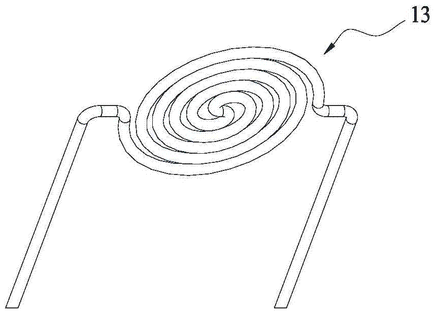
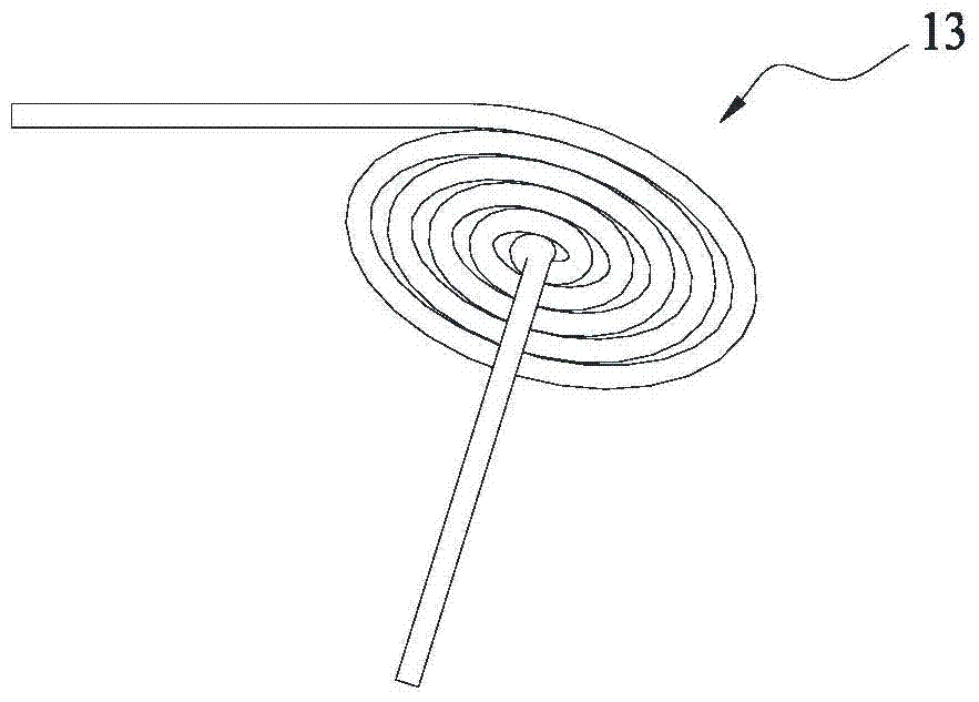
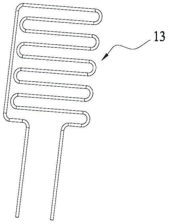
[0053] Such as Figure 5-7 An electronic cigarette vaporizer shown includes a heating component 10 and a conductive component 20. The heating component 10 includes a base 11, a fixing seat 12, a heating wire 13, a liquid storage medium 14 and a liquid conducting medium 15. The base 11 has a vertical through The fixing hole 111 of the base 11 and the first liquid guide hole 112 passing through the base 11 in the transverse direction, the first liquid guide hole 112 communicates with the fixing hole 111, the conductive component 20 is connected to the lower end of the heating component 10; the fixing seat 12 is detachable Sealed and fixed in the fixing hole 111, the fixing seat 12 has an airflow channel 121 vertically penetrating the fixing seat 12, the airflow channel 121 is connected to the two ends of the fixing hole 111, and the fixing seat 12 on the side of the airflow channel 121 A fixed port 122 is opened, and the fixed port 122 is separated from the air flow passage 121 ...


PUM


Abstract

The invention discloses a heating component of an electronic cigarette atomizer, which includes a heating component and a conductive component. The heating component includes a base, a fixing seat, a heating wire and a liquid storage medium. The base has a fixing hole vertically penetrating the base and a horizontal penetrating hole through the base The first liquid guide hole, the first liquid guide hole communicates with the fixed hole, the conductive component is connected to the lower end of the heating component; the fixed seat is sealed and installed in the fixed hole, and the fixed seat has an airflow channel vertically passing through the fixed seat. The channel is connected to the openings at both ends of the fixing hole; the heating wire and the liquid storage medium are installed on the fixing seat, the heating wire is electrically connected with the conductive component, one side of the heating wire is in contact with one side of the liquid storage medium, and the other side of the heating wire One side is opposite to the airflow channel, so that the heating wire is placed outside the airflow channel. The invention can realize sufficient output of smoke to meet the needs of users, and has good taste of smoke, and avoids burnt taste, atomized residual water or smoke liquid being sucked into people's mouth.

Description

technical field [0001] The invention relates to parts of electronic cigarettes, in particular to a heating component of an electronic cigarette vaporizer. Background technique [0002] Electronic cigarettes, also known as atomizers, electronic cigarettes, and virtual cigarettes, are mainly used to quit smoking and replace cigarettes. It has the appearance and taste similar to cigarettes. [0003] The current electronic cigarette is generally composed of a mouthpiece assembly, an atomizer and a liquid storage assembly, and the atomizer includes a heating assembly and a conductive assembly. The heating component generally includes a heating wire and a fiber rope (or a fluid-guiding cotton piece), the heating wire is spirally wound on the fiber rope (or a fluid-guiding cotton piece), and the fiber rope is used to guide the smoke liquid in the liquid storage component. When in use, the heating wire is energized through the conductive component, and the heating wire of the heat...

Claims


Application Information

Patent Timeline
Patent Type & Authority Patents(China)
IPC IPC(8): A24F47/00A24F40/10A24F40/46A24F40/485
CPCA24F40/485A24F40/46A24F40/10
Inventor 朱晓春
Owner SHENZHEN SMACO TECHNOLOGY LIMITED
Why Eureka
Try Eureka