A differential flap rudder control cabin structure

A technology for controlling cabins and cabins, which is applied to aircraft transmissions, aircraft power transmission, aircraft power devices, etc., can solve the problems of unseen technical reports, late start, and the control mode is not a differential control mode, and can solve the problem of installation. bad operation effect

Inactive Publication Date: 2016-05-04
BEIJING AEROSPACE INST OF THE LONG MARCH VEHICLE +1
View PDF4 Cites 0 Cited by
  • Summary
  • Abstract
  • Description
  • Claims
  • Application Information

AI Technical Summary

Problems solved by technology

[0003] At present, foreign countries have conducted relevant technical verifications on the technology of using FLAP rudders for reentry aircraft control, but the control method is not a differential control mode; this type of technology started relatively late in China, and no relevant technical reports have been seen.

Method used


Image

  • A differential flap rudder control cabin structure
  • A differential flap rudder control cabin structure
  • A differential flap rudder control cabin structure

Examples


Embodiment Construction

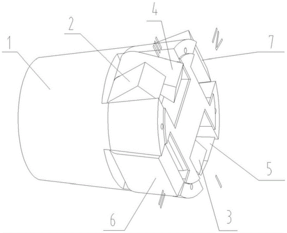
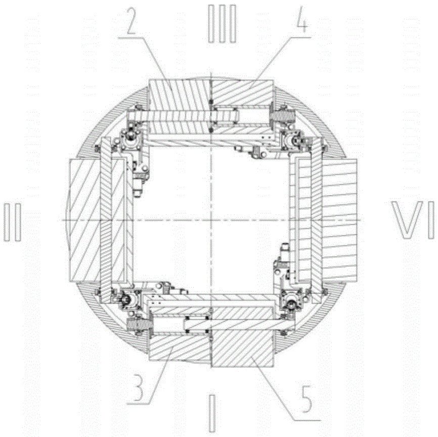
[0018] like figure 1 As shown, the yaw channel II and IV quadrants of the present invention each have a FLAP rudder, and the II rudder 6 and the IV rudder 7 are each driven by an actuator 8; the I quadrant has an I 1 Helm 3 and I 2 Rudder 5, III quadrant has III 1 Helm 2 and III 2 Rudder 4, where I 1 Helm 3 and III 1 Rudder 2 rotates synchronously, driven by an actuator 8, I 2 Helm 5 and III 2 The rudders 4 rotate synchronously, driven by an actuator 8, and the two groups of rudders rotate independently of each other to realize the differential control of the pitch channel.

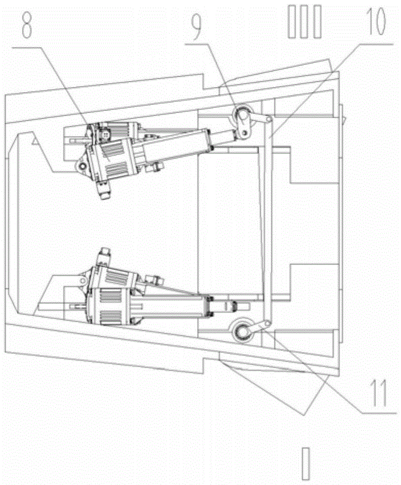
[0019] like figure 2 As shown, an actuator 8 is hinged with the rocker arm I9, the rocker arm I9 is ​​connected with the rotating shaft I19 as a whole, and the rotating shaft I19 and III 1 The rudder 2 is connected by a key, one end of the connecting rod 10 is hinged to the other fulcrum of the rocker arm I9, the other end of the connecting rod 10 is hinged to the rocker arm II11, and the rocker ...


PUM


Abstract

The invention discloses a novel differential FLAP rudder control cabinet structure. The tail of a control cabinet body is provided with two FLAP rudders, being marked as a rudder II and a rudder IV, in quadrant II and quadrant IV of a yaw channel; two coaxial FLAP rudders are arranged in quadrant I, and marked as a rudder I1 and a rudder I2, and two coaxial FLAP rudders are arranged in quadrant III, and marked as a rudder III1 and a rudder III2; a bearing box is arranged at the end, connected with the rudder III1 or the rudder I2, of a revolving shaft I, two angular contact ball bearings are arranged at the other end of the revolving shaft I back to back, the angular contact ball bearings are arranged at one end of a shaft sleeve fixedly connected with the rudder III2 or the rudder I1, and the other end of the shaft sleeve is connected with a connecting shaft on which a bearing box is arranged; the rudder I1 and the rudder III1 are driven to realize synchronous rotation in a manner that a crank-link mechanism is driven by an actuator installed in the control cabinet; the rudder I2 and the rudder III2 are driven to realize synchronous rotation in a manner that a crank-link mechanism is driven by an actuator installed in the control cabinet; the rudder II and the rudder IV are driven by respective actuators installed in the control cabinet.

Description

technical field [0001] The invention belongs to the field of reentry control aircraft design. Background technique [0002] With the development of the times and the advancement of science, the requirements for strike accuracy of reentry vehicles are getting higher and higher, and even strategic reentry vehicles are required to strike precisely. The differential FLAP rudder control module is exactly the reentry control module equipped for the future strategic reentry vehicle. [0003] At present, foreign countries have carried out relevant technical verification on the technology of using FLAP rudder for reentry aircraft control, but the control mode is not the differential control mode; this type of technology started relatively late in China, and there are no related technical reports. Contents of the invention [0004] The technical solution of the present invention is: the four rudders of the pitch channel can realize the synchronous movement of the rudders on the sam...

Claims


Application Information

Patent Timeline
Patent Type & Authority Patents(China)
IPC IPC(8): B64C13/30
Inventor 侯保江水涌涛殷德政孙向春周人歌李晓东李长春黄有旺高凯陈刚
Owner BEIJING AEROSPACE INST OF THE LONG MARCH VEHICLE
Why Eureka
Try Eureka